

Consumer electronics keep getting thinner, smaller, and more integrated. That puts more pressure on PCB design. In products such as smartphones, camera modules, and display assemblies, the board often has to support dense routing, fit into tight mechanical spaces, connect multiple modules, and still remain manufacturable at volume.
That is where rigid-flex PCB design becomes valuable. By combining rigid areas for component mounting with flex areas for folding and interconnection, rigid-flex structures help reduce the number of connectors, save space, and simplify system integration.
But consumer electronics use rigid-flex differently from aerospace and other high-reliability markets. The goal is not maximum reliability at any cost. It is finding the right balance between high density, thin construction, manufacturability, and cost.
Quick Answer
A successful consumer electronics rigid-flex PCB is not the most complex board possible. It is the one that balances:
- high routing density
- thin construction
- controlled layer count
- efficient board shape
- scalable manufacturing
- acceptable reliability at target cost
Why Consumer Electronics Pushed Rigid-Flex PCB Design in a Different Direction
Rigid-flex PCB technology was originally developed for high-reliability electronics, especially in aerospace systems, where dependable routing had to fit within limited space. In some advanced applications, rigid-flex constructions exceeded 30 conductor layers. Those designs were built around reliability rather than extreme miniaturization. They typically used wider traces, larger plated through-holes, and thicker hole-wall copper.
Consumer electronics changed that path.
Smartphones, digital cameras, and compact display systems are in demand:
- more functions in less space
- more interconnect density
- thinner packages
- lower manufacturing cost in high-volume production
As a result, rigid-flex PCB design moved toward thinner materials, smaller via structures, finer features, and more production-efficient process routes. That shift is one of the main reasons consumer electronics rigid-flex PCB design now has its own logic, separate from traditional high-reliability rigid-flex design.
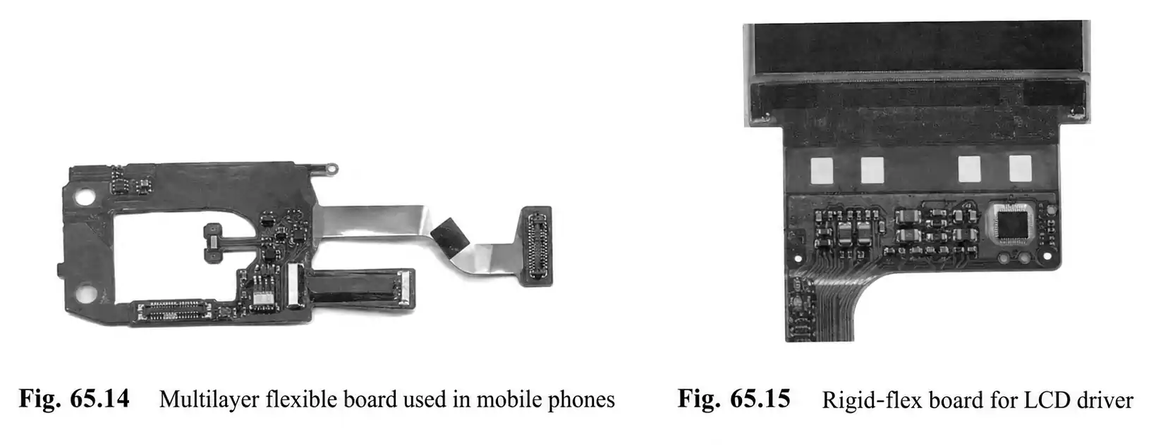
What a Consumer Electronics Rigid-Flex PCB Typically Looks Like
A high-density rigid-flex PCB used in consumer products is usually built for tight packaging and dense assembly.
Typical characteristics include:
- line width below 75 µm
- blind via diameter below 150 µm
- dense SMT assembly
- very small chips mounted in rigid sections
- interconnects that may still carry meaningful current
That last point matters. Even in a very compact design, high density does not eliminate thermal and electrical constraints. Routing still has to account for current, heat, and mechanical reliability.
Typical Role Split: Rigid Section vs. Flex Section
| Rigid section | Component mounting, mechanical support, dense SMT placement |
| Flex section | Folding, turning, cross-module interconnects, space-saving routing |
This is what makes a rigid-flex PCB for consumer electronics so effective. It is not just a bendable board. It is an integrated interconnect structure that reduces the need for separate connectors and cables while improving packaging efficiency and assembly integration.
Example: Smartphone Rigid-Flex PCB in a Display Module
A smartphone rigid-flex PCB used in an LCD control module is a strong example of this architecture.
In that type of structure:
- Control ICs are mounted on rigid areas
- dense SMT components are placed in rigid sections
- Flip-chip devices may also be used
- One flex section may connect to LCD glass through a 150 µm-pitch ACF
- Another flex section may connect into a 0.5 mm-pitch FFC connector
This shows that a display module rigid-flex PCB is not only a layout problem. It also has to support:
- module interfaces
- display interconnect methods
- connector pitch
- assembly flow
- real 3D product packaging constraints
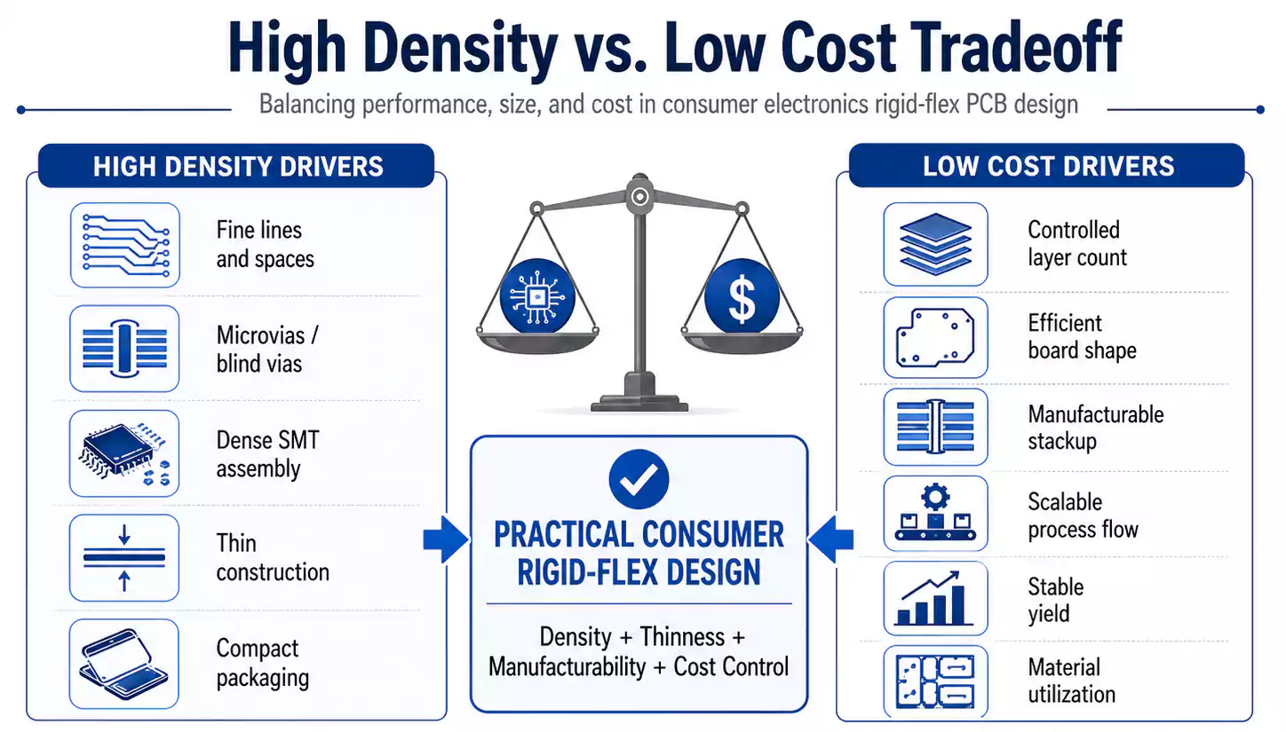
Why High Density and Low Cost Naturally Conflict
This is the core tradeoff in consumer electronics rigid-flex PCB design.
Higher density usually requires:
- finer traces
- smaller vias
- tighter spacing
- thinner constructions
- more advanced processing
Lower cost usually requires:
- fewer layers
- simpler process flow
- higher throughput
- better material utilization
- more stable yield
These goals often work against each other.
Finer traces increase imaging and etching difficulty. Smaller blind vias make laser drilling and plating more demanding. More complex structures raise the burden on dimensional control and production yield. At the same time, if the board becomes too thick, too layered, or too irregular in shape, the cost rises quickly.
For consumer electronics, the real question is not just:
Can this rigid-flex PCB be built?
The real question is:
Can it be built consistently, at scale, and at the right cost?
Consumer Electronics vs. High-Reliability Rigid-Flex PCB Design
| Main goal | Long-term reliability | Density, thinness, and cost balance |
| Materials | Often thicker and more robust | Often thinner and more space-efficient |
| Hole-wall copper | Heavier | Can be lighter if reliability remains acceptable |
| Layer strategy | Higher layer counts possible | Usually kept lower for thickness and cost |
| Structure choice | Reliability-first | Production efficiency matters more |
| Manufacturing focus | Performance margin | Yield, throughput, and cost control |
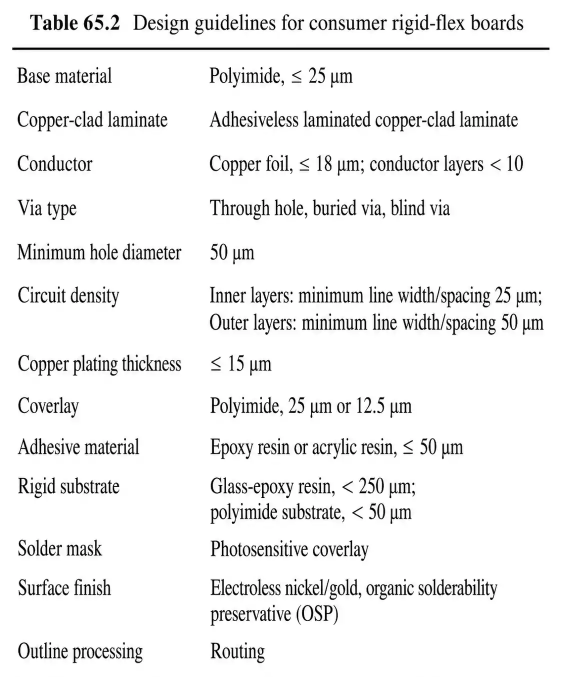
Core Design Strategies for Consumer Electronics Rigid-Flex PCB Design
1. Thin Construction Comes First
A thin rigid-flex PCB is often a first priority in consumer products because miniaturization is a product-level requirement.
High-reliability sectors tend to favor polyimide films thicker than 50 µm for better stability and durability. Consumer electronics increasingly use materials below 50 µm to reduce overall thickness and fit tighter product envelopes.
The benefits of thinner construction include:
- lower overall board thickness
- better fit in thin devices
- thinner rigid SMT areas
- easier integration into folded mechanical assemblies
But thinner is not automatically better. Thin materials are harder to control dimensionally and can deform more during thermal processing. Thickness reduction must remain within a manufacturable window.
2. Hole-Wall Copper Can Be Reduced, but Not Carelessly
In consumer electronics, plated through-hole copper can be thinner than in industrial or aerospace products. Hole-wall copper below 15 µm may be acceptable, provided that reliability remains strong enough for the application.
That does not mean reliability stops mattering.
As the copper thickness decreases, the process margin also gets tighter. Drilling quality, desmear performance, plating uniformity, and structural validation all become more important. This is especially true in dense designs where the via structure directly affects long-term performance.
3. The Rigid Area May Need to Be Re-Engineered
One of the most useful ideas in consumer rigid-flex PCB design is that the rigid section does not always need a traditional thick FR-4-style outer construction.
Possible approaches include:
- replacing some glass-epoxy outer materials with polyimide film
- using adhesiveless rigid-flex PCB materials
- Laminating copper foil plus a single bonding sheet onto a flex core
These approaches help reduce the thickness of rigid sections while still supporting dense component mounting.
In a 6-layer design, the rigid SMT area can be reduced to less than 400 µm in thickness when the structure is optimized carefully.
4. Layer Count Should Stay Under Control
For consumer products, more layers do not necessarily make them better.
A practical rule is to keep the total conductor layers at 10 or fewer when possible. That helps limit board thickness and manufacturing cost.
There is also an important routing principle here:
If the routing pitch is still above 100 µm, reducing the trace and space is often a better move than adding more layers.
Why?
Because additional layers increase:
- thickness
- lamination complexity
- drilling burden
- Overall process cost
5. Board Shape Is a Cost Variable
The board outline affects cost more than many teams expect.
Keeping the overall structure inside a compact square or rectangular area can improve:
- material utilization
- panel efficiency
- manufacturing flow
- cutting efficiency
Irregular or fragmented shapes may still be necessary in some products, but they usually increase manufacturing complexity. In high-volume production, shape optimization can make a meaningful difference in total cost, especially for a low-cost rigid-flex PCB program.
Why Some High-Reliability Structures Do Not Fit Consumer Products
Some multilayer flex structures are excellent for bend reliability.
A good example is the bookbinder-style structure, in which flex layers in the bend region are arranged with progressively shorter lengths from inner to outer layers. That helps maintain more uniform spacing during bending and reduces wrinkling and stress concentration.
The downside is throughput.
Bookbinder-style structures require special tools and processes, and production efficiency is lower. That makes them a poor fit for cost-sensitive, high-volume consumer products.
This leads to an important rule:
Consumer electronics do not need every reliability-enhancing rigid-flex structure.
They need structures that provide sufficient reliability without undermining production efficiency or cost targets.
Rigid-Flex PCB Manufacturing Approaches That Support Both Density and Cost
1. Use Via Structures That Open Routing Space
Buried vias or inner-layer microvia structures can improve internal routing efficiency by freeing space where the design needs it most. In dense consumer layouts, that can be more valuable than simply increasing layer count. This is one reason rigid-flex microvia strategies are so important in compact electronic assemblies.
2. Adhesiveless Materials Are a Strong Fit
Cast or laminated adhesiveless rigid-flex PCB materials are especially useful in dense manufacturing because they help:
- reduce smear
- improve heat resistance
- support repeated high-temperature processing
- reduce total thickness
3. Sequential Build-Up Is a Key High-Density Path
Sequential build-up processing for blind vias has become a standard route for high-density rigid-flex PCB manufacturing.
It helps create:
- finer outer-layer structures
- more routing room
- more flexible via strategies
A practical material combination is often:
- heat-resistant epoxy bonding sheets
- paired with adhesiveless base materials
4. CO2 Laser Microvias Support High Throughput
In building up outer layers, opening copper windows can improve the CO2 laser drilling speed.
Under favorable conditions, a CO2 laser can drill 10,000 blind vias per minute.
That matters because consumer products do not just need dense interconnects. They need dense interconnects that meet mass-production throughput requirements.
5. Desmear Still Matters
Even if hollow-wall copper is lighter, its reliability still depends heavily on hole preparation.
Plasma etching before blind-via plating can improve reliability. This is especially important when acrylic adhesive systems are involved, since conventional permanganate desmear can cause swelling and reduce the reliability.
6. RTR Can Improve Efficiency in the Right Structure
If inner layers do not contain holes, RTR processing can significantly improve throughput.
If inner layers do contain holes, however, RTR requires extremely tight dimensional accuracy control.
7. Profile Method Affects Unit Cost
For board profiling, semi-automatic punching and metal stamping can be more efficient than CNC routing in some high-volume scenarios.
But the design has to be handled carefully. Poor die geometry can create cracks or notches along flex edges.
8. Dimensional Control Is a Major Yield Driver
Even when stable adhesiveless materials are used, thin flex materials can still deform through repeated thermal cycles.
That is why:
- dimensional change must be anticipated at each process step
- Compensation may be needed at multiple stages
- Panel size selection also matters for yield
In practice, many cost problems in rigid-flex PCB manufacturing are yield issues driven by dimensional instability.
What the Smartphone Display Module Example Really Shows
The phone display control module example clearly shows the system-level value of rigid-flex.
It is not just replacing a rigid board.
It is not just replacing an FPC.
It is combining:
- control circuitry
- dense assembly
- LCD interfacing
- camera integration
- folded interconnection
into one integrated structure.
That creates real product-level benefits:
- fewer separate interconnect parts
- fewer connectors
- simpler assembly
- better space utilization
- tighter module integration
For consumer products, those system-level gains often matter more than the narrow cost comparison of one board style versus another.
FAQ
Why are rigid-flex PCBs becoming more common in consumer electronics?
Because products keep getting thinner and more compact, while internal interconnect complexity keeps increasing. A rigid-flex PCB for consumer electronics enables dense routing in a limited space and reduces the need for additional connectors and cables.
What is the main design goal in consumer electronics rigid-flex PCB design?
The goal is not maximum density by itself. It is the right balance among density, thinness, cost, production efficiency, and acceptable reliability.
Do consumer rigid-flex designs always need HDI or microvias?
Not always, but in small, high-density products, rigid-flex microvia and build-up processing are often very helpful because they open routing space and support finer feature integration.
What is the most effective way to reduce costs?
Usually, it is not just about cheaper material. The biggest savings often come from controlling layer count, reducing thickness intelligently, simplifying board shape, improving material utilization, and choosing structures and processes that scale well in production.
Is thinner always better?
No. A thin, rigid-flex PCB helps with miniaturization and packaging, but it also creates additional challenges in dimensional stability, thermal distortion, and yield. Thin design still has to remain manufacturable.
Why are some high-reliability structures not suitable for consumer products?
Because some structures improve bend reliability at the cost of much higher manufacturing complexity and lower production efficiency. In high-volume, cost-sensitive products, that tradeoff is often not worth it.
Final Thoughts
The most effective consumer rigid-flex PCB is rarely the most complex one. It is the one that balances density, thickness, reliability, and manufacturability while still meeting cost and yield targets.
In consumer electronics, rigid-flex is not just a premium PCB option. It is a practical design approach for improving integration, reducing interconnect complexity, and supporting thinner, more efficient products.
For teams developing consumer rigid-flex designs for real production, FastTurn PCB provides manufacturing-focused support and practical build guidance.
