


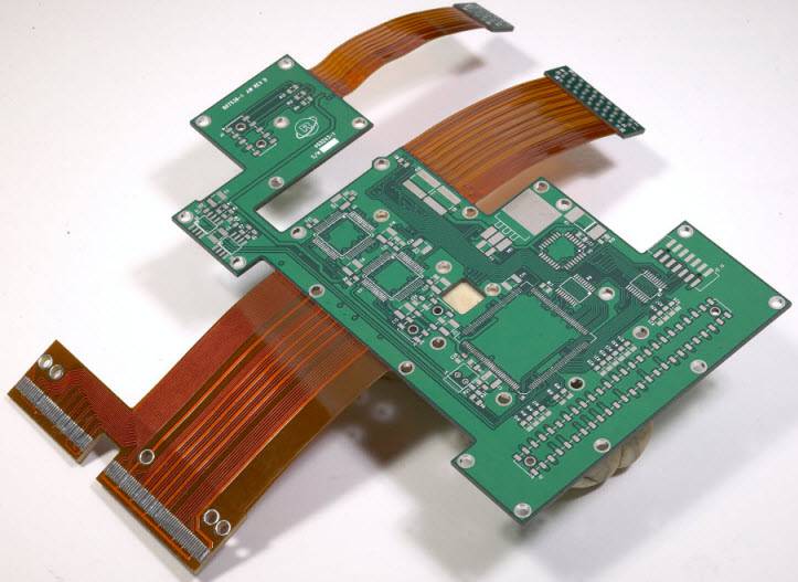
A rigid-flex PCB combines rigid and flexible circuit sections into a single board. It is used when a product needs both mechanical support for components and the ability to bend or fold within a limited space.
Compared with separate rigid boards connected by cables or connectors, a rigid-flex design can reduce interconnects, save space, lower weight, and improve reliability.
This article explains what a rigid-flex PCB is, how it works, where it is used, and the basic design considerations beginners should know.
What Is a Rigid Flex PCB?
A rigid-flex PCB is a printed circuit board that combines rigid and flexible circuit materials into a single unified structure.
- The rigid sections provide mechanical support for components and connectors.
- The flexible sections allow the board to bend, fold, or fit into a three-dimensional space.
In a standard electronic assembly, separate rigid boards are often connected by cables or wire harnesses. In a rigid-flex design, those separate interconnects can often be replaced by integrated flex sections. This creates a cleaner, more compact internal layout.
Typical Materials Used
| Rigid section | FR-4 | Supports components and keeps the board structurally stable |
| Flex section | Polyimide | Allows bending and improved flexibility |
| Conductive layer | Copper | Carries electrical signals |
Rigid-flex PCBs are often used in products where:
- Space is limited
- Reliability is critical
- The internal structure is not flat.
- connectors and wiring need to be reduced
In many applications, the flexible part is bent only once during installation and then remains in place. In others, the flex area may need to tolerate repeated movement, which requires more careful design.
How a Rigid Flex PCB Works
The easiest way to understand a rigid-flex PCB is to think of it as a board with different jobs in different areas.
Rigid Sections
The rigid sections act like a traditional PCB. These are the areas where components such as:
- ICs
- connectors
- sensors
- resistors
- capacitors
are mounted.
These sections provide the physical strength needed for assembly, soldering, and long-term support.
Flexible Sections
The flexible sections act as built-in interconnects between rigid areas. Instead of using separate wiring or connectors, the traces continue through the flexible part of the circuit.
This allows the board to:
- bend around corners
- fold into tighter spaces
- connect different sections of a product
- maintain electrical continuity without separate cables
Key Benefits of Rigid Flex PCBs
Rigid-flex PCBs are popular because they offer practical advantages in both electrical and mechanical design.
1. Space Savings
Because the board can bend and fold, it can fit into product shapes that would be difficult for a traditional flat rigid board.
This is especially important in compact electronics where internal space is limited and every millimeter matters.
2. Fewer Connectors and Less Wiring
In many conventional assemblies, multiple boards are connected with:
- cables
- ribbon wires
- board-to-board connectors
A rigid-flex structure can eliminate some of these parts by integrating the connections directly into the PCB.
3. Lower System Weight
Replacing heavy connectors and extra wiring with an integrated board structure can reduce overall system weight.
This matters in:
- portable devices
- aerospace systems
- medical equipment
- compact industrial products
4. Better Reliability
Connectors and wires are often vulnerable to:
- vibration
- mechanical stress
- installation errors
- wear over time
A properly designed rigid-flex board can provide more stable electrical connections and better resistance to shock or vibration.
5. Simpler Assembly
Instead of aligning and connecting multiple boards during manufacturing, the product may use a single integrated circuit assembly that folds into place.
This can:
- reduce assembly steps
- improve consistency
- simplify installation
6. More Mechanical Design Freedom
Rigid-flex PCBs make it easier to design electronics around the product's shape rather than forcing the product to fit a flat board.
That can support:
- better packaging efficiency
- more creative industrial design
- improved use of internal space
Quick Summary of Benefits
| Space saving | Fits into compact and irregular enclosures |
| Fewer connectors | Reduces failure points |
| Lower weight | Helpful in portable and aerospace products |
| Better reliability | Improves resistance to vibration and stress |
| Simpler assembly | Reduces wiring and installation complexity |
| Design flexibility | Supports 3D packaging and folding layouts |
Common Applications of Rigid-Flex PCBs
Rigid-flex PCBs are used in many industries, especially where space, weight, and reliability are major design concerns.
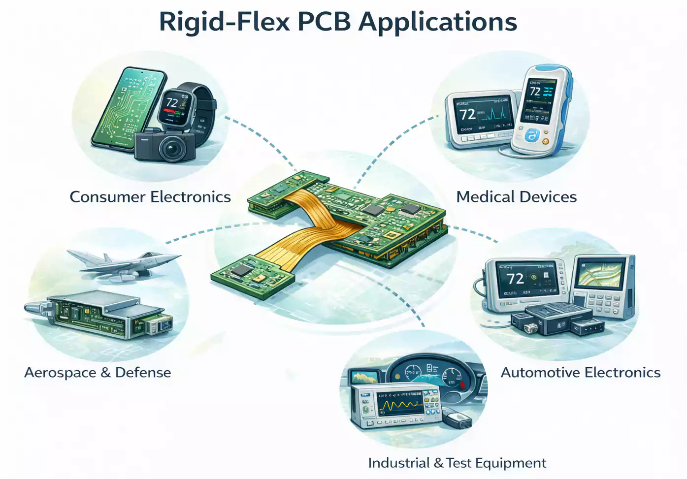
Consumer Electronics
Rigid-flex boards are often used in:
- smartphones
- cameras
- wearables
- compact personal electronics
These products need dense packaging and highly efficient use of limited internal space.
Medical Devices
Medical products often require compact designs and dependable electrical performance. Rigid-flex PCBs are used in:
- portable monitors
- diagnostic equipment
- imaging systems
- handheld medical devices
Aerospace and Defense
In aerospace and defense systems, rigid-flex boards help reduce weight while improving resistance to vibration and mechanical stress.
These applications also often involve constrained spaces and demanding reliability requirements.
Automotive Electronics
Rigid-flex PCBs can be useful in automotive systems where packaging is tight, and the electronics must survive vibration or movement.
Common examples include:
- sensors
- control systems
- lighting modules
- display-related electronics
Industrial and Test Equipment
They are also common in industrial equipment, smart control products, and test systems, where complex mechanical packaging makes traditional rigid board layouts impractical.
Application Overview
| Consumer electronics | Saves space in compact devices |
| Medical | Supports lightweight, reliable assemblies |
| Aerospace and defense | Reduces weight and improves durability |
| Automotive | Handles vibration and tight packaging |
| Industrial equipment | Fits complex mechanical structures |
Rigid Flex PCB Manufacturing Basics
Rigid-flex PCBs are more complex to manufacture than standard rigid PCBs because they combine rigid and flexible materials in a single structure.
The rigid and flex sections behave differently during lamination, drilling, handling, and assembly, so the process requires tighter control to maintain layer alignment and electrical reliability.
Why Manufacturing Is More Complex
Rigid-flex boards typically require:
- specialized materials
- more careful stack-up design
- tighter process control
- better transition design between rigid and flex areas
Material selection is also more critical. Rigid sections usually use standard rigid laminates, while flex sections use flexible dielectric materials and coverlay systems.
Why Cost Is Higher
Rigid-flex PCBs usually cost more because the fabrication process is more specialized, the materials are more expensive, and manufacturability requirements are tighter.
However, a higher board cost does not necessarily translate into a higher product cost. In some designs, fewer connectors, less wiring, and simpler assembly can offset the added PCB fabrication cost.
For that reason, rigid-flex is often selected not just for flexibility, but for better overall product efficiency.
Basic Design Considerations for Beginners
If you are new to Rigid flex PCB design, the first rule is simple: do not treat the flex area like a standard rigid board.
The flex region is subject to mechanical stress, so the layout must support bending without damaging the circuit.
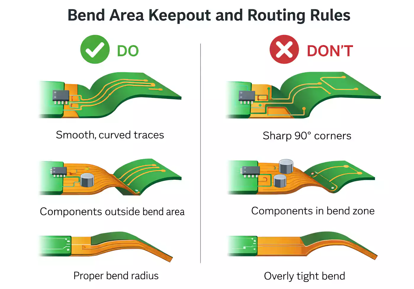
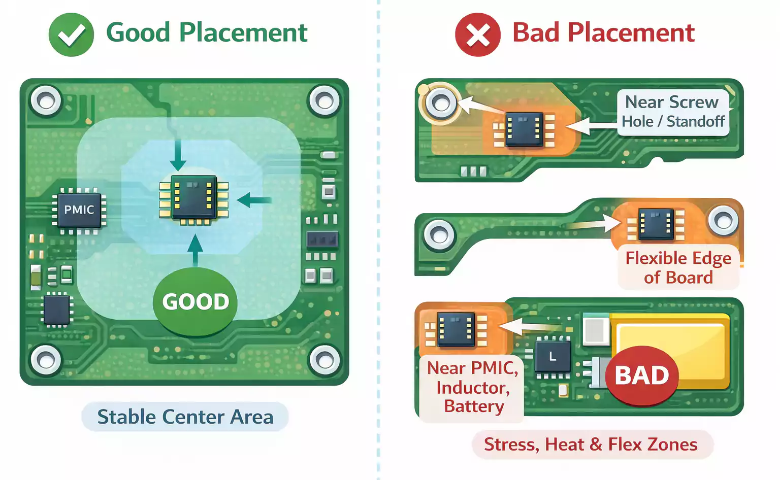
1. Keep Bend Areas Clear
Bend areas should remain as simple as possible. Avoid placing these features in flex zones whenever possible:
- components
- vias
- stressed pads
- heavy copper features
2. Use Smooth Trace Routing
Sharp corners can concentrate stress and reduce reliability. In flex areas, smooth routing is generally preferred.
3. Choose Copper Thickness Carefully
Thinner copper is often used in flex regions to improve flexibility and reduce strain during bending.
4. Control Bend Radius
A flex section should not be bent too tightly. An insufficient bend radius can overstress the copper and dielectric materials, increasing the risk of cracks, delamination, or electrical failure.
The required bend radius depends on the stack-up, copper thickness, and whether the bend is static or dynamic.
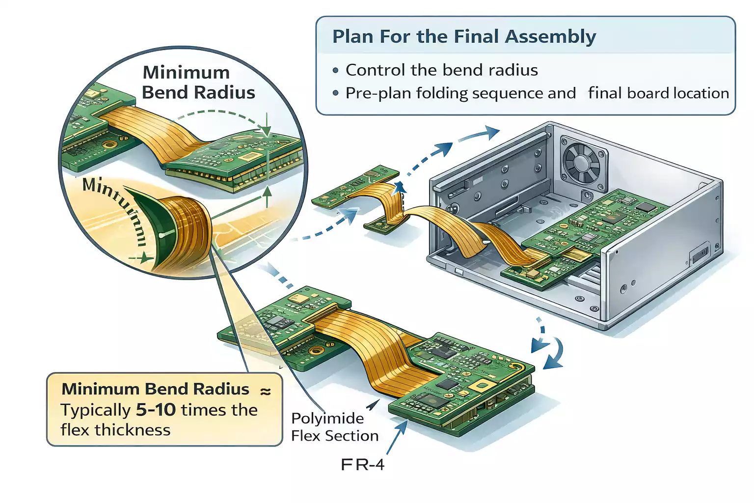
5. Design for the Final Assembly
Rigid-flex design is both an electrical and a mechanical problem. The folding sequence, enclosure size, and final board position should be considered early in the design process.
Without that planning, the design may be difficult to manufacture or assemble correctly.
6. Involve the Manufacturer Early
Early DFM review is especially important for rigid-flex projects. An experienced rigid flex pcb manufacturer can help identify issues with stack-up, bend areas, material selection, and fabrication limits before they become costly problems.
Is a Rigid Flex PCB Right for Your Project?
Rigid-flex PCBs are not the right choice for every product.
If your design is:
- simple
- flat
- spacious
- cost-sensitive
Then a standard rigid PCB may be the better option. It is usually less expensive and easier to design and build.
But rigid flex may be a very smart choice if your product has:
- tight packaging
- unusual mechanical geometry
- connector-related reliability concerns
- a need to reduce wiring
- a folding or 3D assembly requirement
The best choice depends on the entire system, not just the PCB. In many successful products, rigid-flex is selected because it improves the overall product design, not simply because it is a more advanced PCB type.
FAQ
What is a rigid-flex PCB?
A rigid-flex PCB combines rigid and flexible sections into a single board. It is used when a product needs both component support and the ability to bend or fold within a limited space.
What is the difference between a flex PCB and a rigid-flex PCB?
A flex PCB is fully flexible. A rigid-flex PCB includes both flexible sections and rigid areas for mounting components.
Why are rigid-flex PCBs more expensive?
They usually cost more because they require specialized materials, a more complex stack-up design, and tighter manufacturing control.
Where are rigid-flex PCBs used?
They are commonly used in consumer electronics, medical devices, automotive electronics, aerospace systems, and other compact or high-reliability products.
Are rigid-flex PCBs more reliable?
They can be more reliable than multi-board assemblies because they reduce the number of connectors, cables, and other interconnect points.
Conclusion
Rigid flex PCB combines rigid support and flexible interconnects in a single board. For products that need compact packaging, fewer interconnects, lower weight, and higher reliability, they can offer clear advantages over traditional multi-board assemblies.
They also require more careful design, manufacturing, and mechanical planning. While rigid-flex PCBs are not always the lowest-cost option at the board level, they are often the better choice at the product level.
Understanding these basics is the first step toward effectively using rigid-flex technology. When the design moves into production, working with an experienced rigid flex PCB manufacturer such as FastTurnPCB can improve manufacturability and overall project reliability.
