


In PCB mechanical drilling, the drill bit does much more than simply create a hole. It directly affects hole position accuracy, hole wall quality, tool breakage risk, and overall drilling cost. As PCB products continue to demand higher drilling quality, PCB drill bit types and structures have evolved beyond traditional designs.
This article explains the most common PCB drill bit types and the key points of PCB drill bit regrinding, helping readers better understand drill bit selection, structural differences, and tool maintenance in PCB manufacturing.
Common Ways to Classify PCB Drill Bit Types
PCB drill bit types can be classified in several different ways, including shank diameter, overall dimensions, cutting-edge and flute design, and front-end shape. Each classification reflects different machine requirements, drilling characteristics, and cost considerations.
1. Classification by Shank Diameter
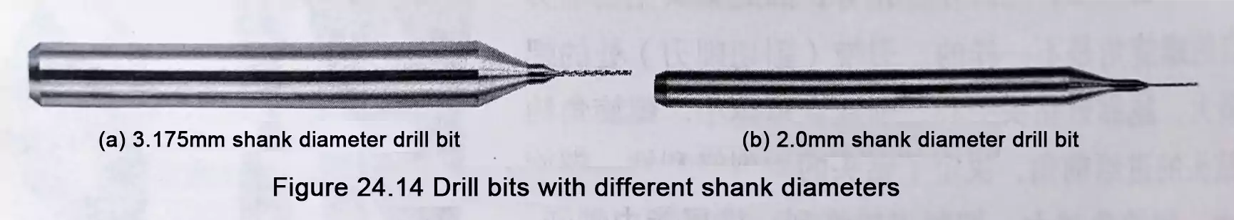
Based on customer machine requirements, commonly used PCB drill bits are generally divided into two categories by shank diameter:
- 3.175 mm shank drill bits
- 2.0 mm shank drill bits
Shank diameter primarily affects spindle and collet compatibility, making it one of the most basic drill bit specifications in PCB processing.
2. Classification by Overall Dimensions
Based on overall dimensions, PCB drill bit types can usually be divided into two groups:
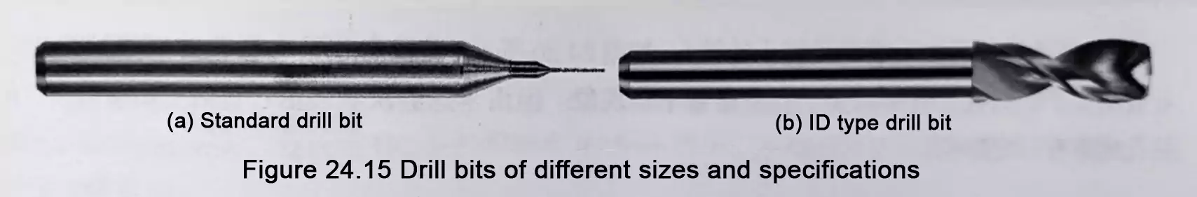
Standard-Type Drill Bits
These are drill bits whose drill diameter is less than or equal to the shank diameter:
Drill diameter ≤ shank diameter
ID-Type Drill Bits
These are drill bits whose drill diameter is greater than the shank diameter:
Drill diameter > shank diameter
This classification reflects the dimensional relationship between the cutting portion and the shank, which can influence the application range and drilling behavior.
PCB Drill Bit Types by Cutting Edge and Flute Design
Conventional PCB drill bits are typically designed with two cutting edges and two flutes. However, as the PCB industry has placed increasingly stringent demands on drilling quality—especially in areas such as hole position accuracy and hole wall roughness—new drill bit designs have been developed, including two-edge one-flute and one-edge one-flute designs.
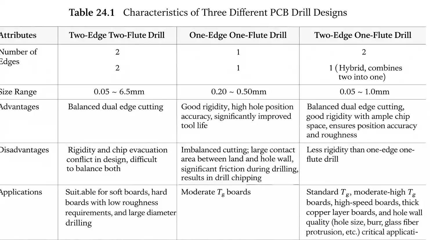
Based on the number of cutting edges and flutes, PCB drill bit types can generally be divided into three categories:

1. Two-Edge Two-Flute Drill
This is the most traditional and widely used drill structure. It is the standard design for conventional PCB drilling and remains common in routine manufacturing applications.
2. Two-Edge One-Flute Drill
This type is one of the newer structural designs developed from the traditional drill format. As drilling quality requirements have increased, this design has been introduced to help meet higher process standards.
3. One-Edge One-Flute Drill
This is another newer drill design developed to support improved drilling quality under certain process conditions. Like the two-edge one-flute structure, it reflects the industry’s effort to optimize drill performance for more demanding applications.
Overall, the evolution of cutting-edge and flute design is driven by the need to better balance several critical factors:
- hole position accuracy
- hole wall quality
- cutting stability
- tool breakage risk
- processing efficiency and cost
In other words, PCB drilling design is no longer just about making holes. It is increasingly about making holes more accurately, more consistently, and with fewer defects.
Classification by Front-End Shape: ST vs UC Drill Bit
In addition to edge and flute configuration, the front-end shape of the drill bit is another important classification method in PCB drilling. Based on front-end geometry, PCB drill bit types can be divided into two main groups:
- ST (Straight Drill) type
- UC (Under Cut Drill) type
The difference between ST vs UC drill bit design is especially important when evaluating drilling heat, hole wall contact, regrinding life, and drilling cost.
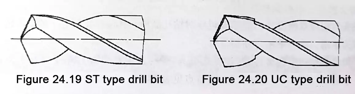
1. ST-Type Drill Bit
An ST drill is a conventional drill bit whose body generatrix is straight. In simple terms, it is a standard straight-body drill.
Its main characteristics are as follows:
Disadvantages
- The contact area between the drill and the hole wall is relatively large.
- A large amount of cutting heat is generated during drilling.
- Excessive cutting heat can lead to poor hole wall quality.
Advantages
- Simple to manufacture
- Can be reground more times
- Offers better overall rigidity
Because of these characteristics, ST drill bits are easier to produce and offer better regrinding life, making them favorable from a cost and rigidity standpoint. However, their larger contact area and higher heat generation can be a disadvantage when higher hole wall quality is required.
2. UC-Type Drill Bit
A UC drill bit has a reduced diameter at the rear section of the drill body.
Its main characteristics include:
Advantages
- Smaller contact area between the drill and the hole wall
- Effectively reduces cutting heat during drilling.
- Helps reduce hole wall defects and improve hole quality
Disadvantages
- Can be reground significantly fewer times than ST drill bits
- May increase drilling cost
This means UC drill bits are better suited for applications where hole wall quality is a priority. By reducing the contact area and cutting heat, they help improve drilling quality. However, this performance advantage comes with reduced regrinding life and potentially higher tool cost.
3. Key Differences in ST vs UC Drill Bit Design
From a practical standpoint, the main differences in ST vs UC drill bit design can be summarized as follows:
Contact Area
- ST: larger
- UC: smaller
Cutting Heat
- ST: higher
- UC: lower
Hole Wall Quality
- ST: more likely to cause hole wall defects
- UC: better for improving hole wall quality
Regrinding Capability
- ST: more regrinds possible
- UC: fewer regrinds possible
Cost
- ST: generally more cost-effective in terms of tool reuse
- UC: typically higher cost due to shorter regrinding life
As a result, choosing between ST and UC drill bits often comes down to balancing drilling quality requirements against tool usage cost.
Key Points in PCB Drill Bit Regrinding
In PCB drilling, drill bits are not always used only once. To improve tool utilization and control cost, used tools are often reground. However, PCB drill bit regrinding is not just about sharpening the tip. It is a critical process that directly affects drilling quality and the risk of tool breakage.
The main control points for PCB drill bit regrinding can be understood in three aspects: regrind amount, regrind quality, and the number of regrinds.
1. Regrind Amount: More Than Just the Cutting Edge
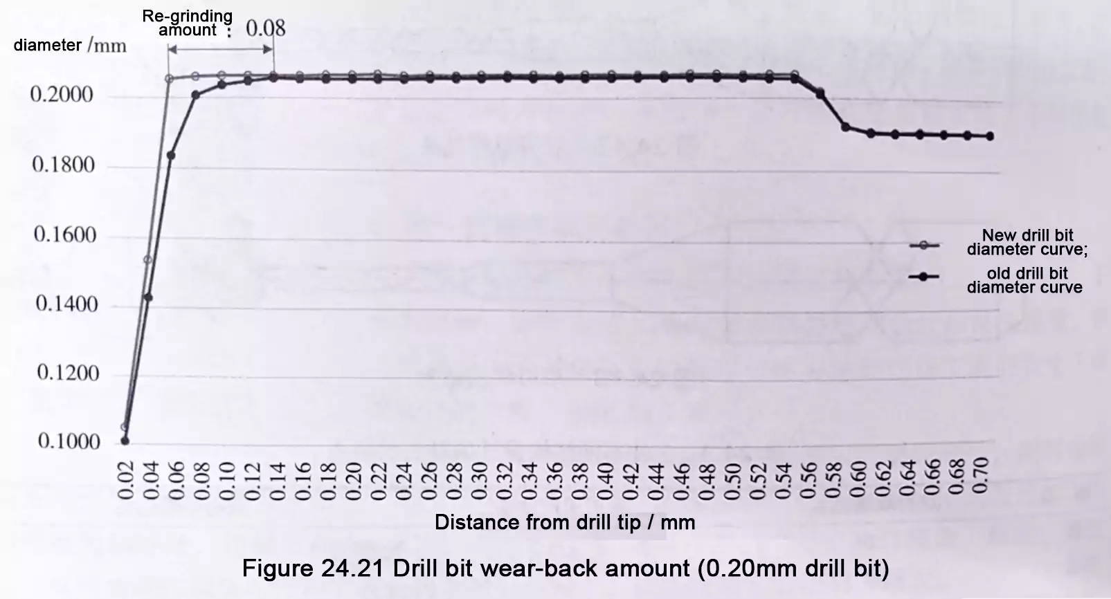
After use, both the cutting face and the margin of the drill bit will wear. During regrinding, it is not enough to remove only the wear on the cutting face. A certain length must also be ground away in order to remove wear on the margin. This required removal length is called the regrind amount.
This means PCB drill bit regrinding is not simply about restoring sharpness at the tip. The worn portion of the full cutting area must be properly removed. If the regrind amount is insufficient, worn areas may remain and continue to affect drilling performance.
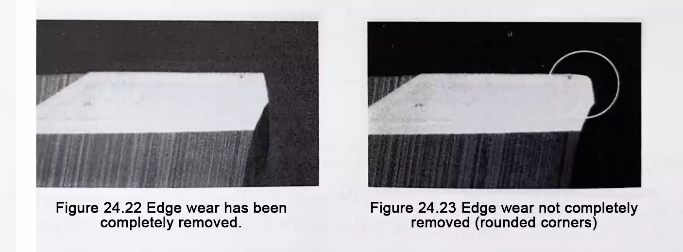
2. Regrind Quality: Worn Edge Areas Must Be Fully Removed
After regrinding, the worn edge area must be completely removed. Otherwise, several problems may occur:
- Reduced hole position accuracy
- poor hole wall quality
- In severe cases, drill breakage
In other words, poor PCB drill bit regrinding quality does not just reduce tool performance. It can also introduce serious process and quality risks when the drill is returned to production.
3. Number of Regrinds: UC Drill Bits Require Special Attention
For UC drill bits, the allowable number of regrinds cannot be judged simply by how many times the bit has already been reground. The key factor is whether the UC head length remains sufficient.
That means:
- The UC section must not become too short.
- The regrinding limit is determined by the UC head length.
This is an important point in tool control. Although UC drill bits provide better hole quality, they are more sensitive to dimensional changes after regrinding and therefore require tighter management.
4. UC Head Length Requirement for Small-Diameter Drill Bits
For drill bits with 0D ≤ 0.50 mm, it is generally recommended to keep the UC head length at 0.25 mm or greater.
If the UC head becomes too short, it may cause:
- poor hole quality
- undersized holes
This shows that in small-hole drilling, dimensional control after regrinding is especially important. Even if the bit can still physically drill, an insufficient UC head length may already be enough to cause hole-quality problems.
How PCB Drill Bit Types and Regrinding Are Connected
PCB drill bit types and regrinding management should not be treated as separate issues. In practice, they are closely linked.
For example:
- ST drill bits offer better rigidity and more regrinding opportunities, making them more suitable where tool life and cost efficiency are important.
- UC drill bits are better suited to applications that require better hole-wall quality, but their regrinding life is more limited because the UC head length must be maintained.
- New edge and flute designs reflect the industry’s growing focus on hole position accuracy, surface quality, and drilling stability.
- Regrind amount and regrind quality directly determine whether a reground bit can still meet process requirements.
From a manufacturing perspective, a drill bit should not be evaluated only by whether it can still drill. It must also be judged by whether it can still achieve the required hole quality. In high-density and high-precision PCB production, drill structure selection and PCB drill bit regrinding standards can directly affect both yield and cost.
FAQ
What are the main PCB drill bit types?
The main PCB drill bit types can be classified by shank diameter, overall dimensions, cutting-edge and flute design, and front-end shape. Common examples include 3.175 mm and 2.0 mm shank drill bits, standard-type and ID-type drill bits, and ST and UC drill bits.
What is the difference between ST and UC drill bits?
In the ST vs UC drill bit comparison, ST drill bits have a straight body and generally offer better rigidity and more regrinds. UC drill bits have a reduced rear body diameter, which reduces contact with the hole wall, reduces cutting heat, and improves hole wall quality.
Why is PCB drill bit regrinding important?
PCB drill bit regrinding helps restore drilling performance and extend tool life. Proper regrinding can reduce drilling costs, but it must fully remove worn cutting-face and margin areas to avoid hole-quality issues and tool breakage.
How many times can a PCB drill bit be reground?
The allowable number of regrinds depends on the drill bit design and remaining geometry. For UC drill bits, the limit is mainly determined by UC head length, as excessive shortening can affect hole quality and size.
What happens if the regrinding quality is poor?
Poor regrinding can lead to reduced hole-position accuracy, poor hole-wall quality, undersized holes, and even drill breakage. That is why regrinding quality control is critical in PCB drilling operations.
Which drill bit type is better for hole wall quality?
UC drill bits are generally preferred for higher hole wall quality because they reduce contact area and cutting heat, though they usually allow fewer regrinds than ST drill bits.
Conclusion
Understanding PCB drill bit types is important for selecting the right tool structure, improving drilling quality, and controlling tool life in PCB manufacturing. From shank diameter and overall dimensions to flute design and front-end geometry, each drill bit type is developed to meet different process requirements.
At the same time, PCB drill bit regrinding plays a critical role in maintaining drilling performance. In ST vs UC drill bit applications, UC drills offer advantages in reducing cutting heat and improving hole wall quality, but they also require tighter control of regrinding limits. Proper drill bit selection and regrinding management are both essential for achieving stable hole quality and cost-effective production.
