


In advanced electronics, simply mounting integrated circuits (ICs) on a printed circuit board (PCB) is no longer enough to meet the extreme demands of size, speed, and reliability.
To overcome these physical and electrical limits, engineers developed the multi-chip module (MCM) — a compact, high-density packaging technology that integrates multiple bare chips onto a single substrate.
Essentially, an MCM is a miniaturized, high-precision PCB, but, from a packaging perspective, it’s a Level-3 system-level package that bridges the gap between conventional IC packages and the carrier PCB.
This article explains what an MCM is, why it’s used, and how different MCM types are designed and manufactured.
What Is a Multi-Chip Module (MCM)?
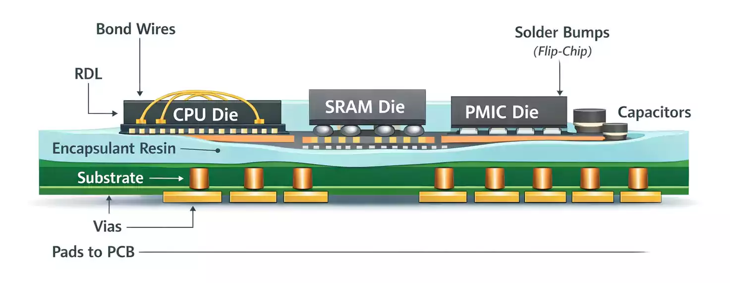
A multi-chip module (MCM) is a packaging technique in which multiple bare dies are mounted directly on a shared substrate, rather than each being enclosed in its own package.
Key Characteristics
- Eliminates individual IC packaging housings
- Allows multiple chips to share one high-density substrate
- Significantly shortens interconnect paths between chips.
- Reduces parasitic inductance and capacitance
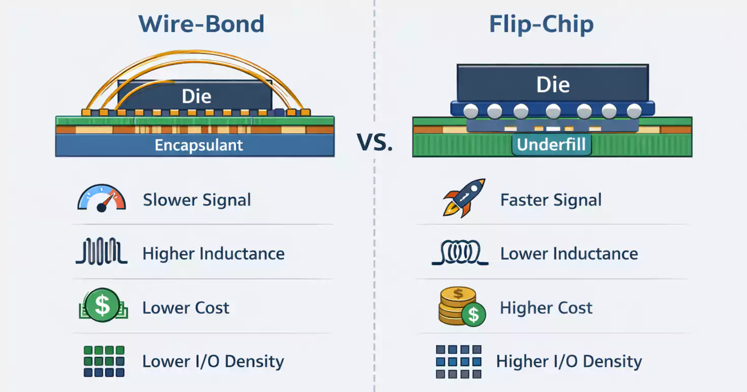
Common Interconnection Methods
- Wire bonding
- Flip-chip bonding
- Tape Automated Bonding (TAB)
- Flip-TAB bonding
Why Use Multi-Chip Modules?
The motivation for adopting MCM technology centers on miniaturization, performance, and integration.
1. Miniaturization and Weight Reduction
By removing the individual chip packages, MCMs dramatically shrink overall system size and weight — essential for aerospace, defense, and compact consumer electronics.
2. High-Speed Performance
High-speed signals degrade quickly across long PCB traces.
MCMs minimize interconnect distance between chips, enabling much faster signal propagation and cleaner high-speed performance.
3. System-Level Integration
MCMs allow designers to integrate multiple functions or chips into a single, compact module — improving performance while simplifying system assembly.
MCM and Packaging Levels
In the electronic packaging hierarchy:
| Level 1 | Single-chip encapsulation | Plastic IC package, PGA |
| Level 2 | Component-to-PCB assembly | Various PCB types |
| Level 3 | System-level packaging | Multi-chip module (MCM), hybrid systems |
MCMs belong to Level-3 packaging, situated between IC packages and the carrier PCB.
That also means MCMs involve more complex design, tighter manufacturing tolerances, and higher cost than standard PCB-based assemblies.
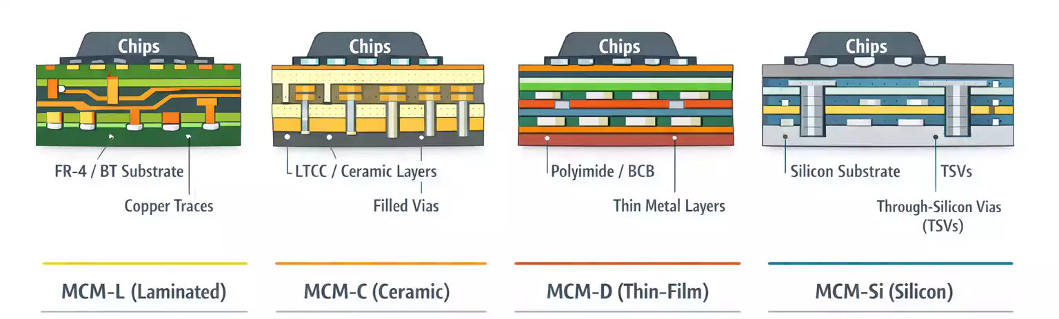
Types of Multi-Chip Modules
Multi-chip modules are classified by substrate material and manufacturing method.
The five most common types are MCM-L, MCM-C, MCM-D, MCM-D/C, and MCM-Si.
1. MCM-L: Laminated Multi-Chip Module
Technical Overview:
- Uses thin laminated substrates with delicate metal layers
- Built with standard PCB fabrication processes
- Finer holes, pads, and trace widths
- Often fabricated using tools similar to those used in semiconductor production.
Advantages:
- Lowest-cost MCM type
- Mature, easily scalable process.
- Compatible with existing PCB design tools and workflows
MCM-L offers the best balance of cost and manufacturability.
2. MCM-C: Ceramic Multi-Chip Module
Process Description:
- Conductive layers patterned on unfired ceramic tape
- Through-holes punched and filled.
- Layers stacked and co-fired to form a multilayer ceramic substrate.
Key Features:
- Higher cost than MCM-L but cheaper than thin-film MCMs
- Excellent thermal stability and reliability
- Proven technology — used for decades in IBM mainframes
PCB design tools and methodologies can be easily adapted for ceramic MCMs.
3. MCM-D: Thin-Film Multi-Chip Module
Technology Approach:
- Alternating layers of thin dielectric and metal films
- Deposited on substrates such as silicon, ceramic, or metal
- Very similar to IC metallization processes
Advantages:
- Extremely high interconnect density
- Outstanding thermal conductivity
- Ideal for high-frequency, high-performance applications
Limitations:
- Requires advanced design and fabrication equipment
- High cost and limited process availability
4. MCM-D/C: Thin-Film / Co-Fired Hybrid MCM
This hybrid MCM combines:
- A co-fired multilayer ceramic substrate, and
- Thin-film interconnect layers are deposited on top.
Engineering Challenges:
- Complex material compatibility
- Mismatch in thermal expansion coefficients
- High manufacturing difficulty and cost
Typically used in defense or aerospace systems that demand both ceramic durability and thin-film precision.
5. MCM-Si: Silicon Substrate Multi-Chip Module
Concept:
- Uses silicon wafers as the substrate
- Metal patterns (aluminum or copper) formed on silicon dioxide
- Fabrication methods are nearly identical to those used in integrated circuit manufacturing.
Unique Advantages:
- Perfect thermal match with IC dies.
- Excellent thermal conductivity
- Superior reliability even under extreme temperature conditions
High tooling cost and limited scalability, but unmatched in performance for specialized, high-end systems.
Summary: Engineering Tradeoffs in MCM Design
Performance vs. Cost
MCMs provide unmatched electrical and mechanical performance:
- Reduced size and weight
- Lower signal delay and crosstalk
- Better overall reliability
However, these benefits come at the cost of:
- Increased design complexity
- High manufacturing cost
- Lower production yield
Integration vs. Fabrication Feasibility
For most mass-market applications, higher single-chip integration (SoC) is more cost-effective than using multiple discrete dies in an MCM.
However, for low-volume or specialized systems, such as:
- Aerospace and defense electronics
- High-performance computing modules
- Custom graphics or video processors
MCMs remain the optimal solution due to their ability to integrate chips built with different process technologies — such as analog + CMOS or ECL + CMOS — within one module.
Conclusion
The multi-chip module (MCM) represents a key milestone in the evolution of electronic packaging — merging the flexibility of PCBs with the density and precision of semiconductor fabrication.
MCMs enable engineers to achieve system-level integration, faster performance, and superior thermal reliability in compact form factors.
While their cost and complexity limit mass adoption, MCM technology continues to power mission-critical, high-performance systems where traditional PCBs can’t compete.
