


Whether you’re designing battery-powered systems, automotive electronics, or industrial control circuits, understanding latching relays is essential for efficient, reliable switching. Unlike traditional relays, latching relays conserve power and maintain their state even after the driving signal is removed. This makes them especially valuable in low-power or memory-dependent applications.
What Is a Latching Relay?
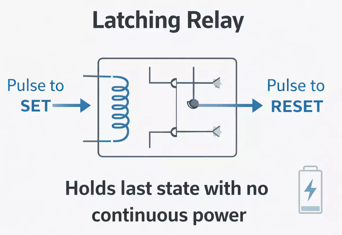
A latching relay (also called a bistable relay) is an electromechanical switch that stays in its last position — either ON or OFF — without requiring continuous electrical power to the coil.
In other words, once the relay is switched to a new state with a short control pulse, it latches in that position and doesn’t change back until a reset signal arrives.
That ability to “remember” a state without ongoing power makes latching relays ideal for systems where power efficiency matters — like battery-powered devices or circuits that should retain their output position after a power loss.
How Does a Latching Relay Work?
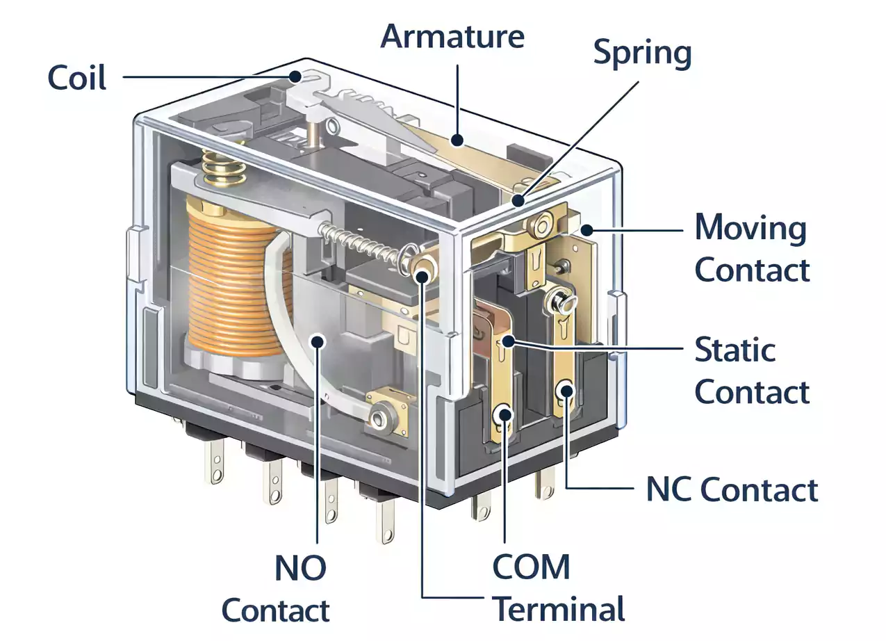
At its core, a latching relay still uses the same electromechanical principles found in traditional relays: a coil creates a magnetic field that moves movable contacts to open or close a circuit. What makes latching relays different is how they stay in position.
Two Stable States
A latching relay has two stable states:
- Set (ON)
- Reset (OFF)
Once switched to either state by a brief electrical pulse, it stays there even if the power is removed.
Single-Coil vs. Dual-Coil Designs
There are two common ways that latching relays achieve this:
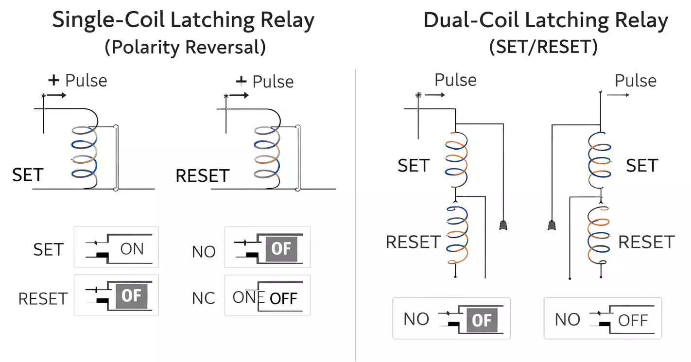
- Single-Coil (Polarity Reversal) Latching Relay
The coil is driven by reversing the voltage polarity. A positive pulse sets the relay, and a negative pulse resets it. This design uses only one coil and changes state depending on the direction of current flow. - Dual-Coil (Set/Reset) Latching Relay
This type has separate “set” and “reset” coils. Each coil receives its own one-shot pulse: one for turning ON, the other for turning OFF. Both coils remain unpowered once the relay latches in its position.
Both designs eliminate the need for continuous coil energization, thereby lowering power consumption and reducing coil heating.
Latching Relay vs. Non-Latching Relay
To understand when to use a latching relay, let’s compare it with the more common non-latching relay:
| Holds state without power | ✅ Yes | ❌ No |
| Requires constant coil power | ❌ No | ✅ Yes |
| Power consumption during hold | Very low | Higher |
| Typical use case | Memory, battery systems | On-off control |
| Behavior on power loss | Retains last state | Returns to default |
Latching models are often better for systems that need stable states without continuous power, such as remote, solar, or vehicle applications.
12V Latching Relay Wiring: Practical Examples
Many real-world projects use 12V latching relay — especially in automotive systems, RV electronics, battery backup controllers, and solar installations — because 12V DC is a widely available power standard.
Here are reliable wiring examples you can follow:
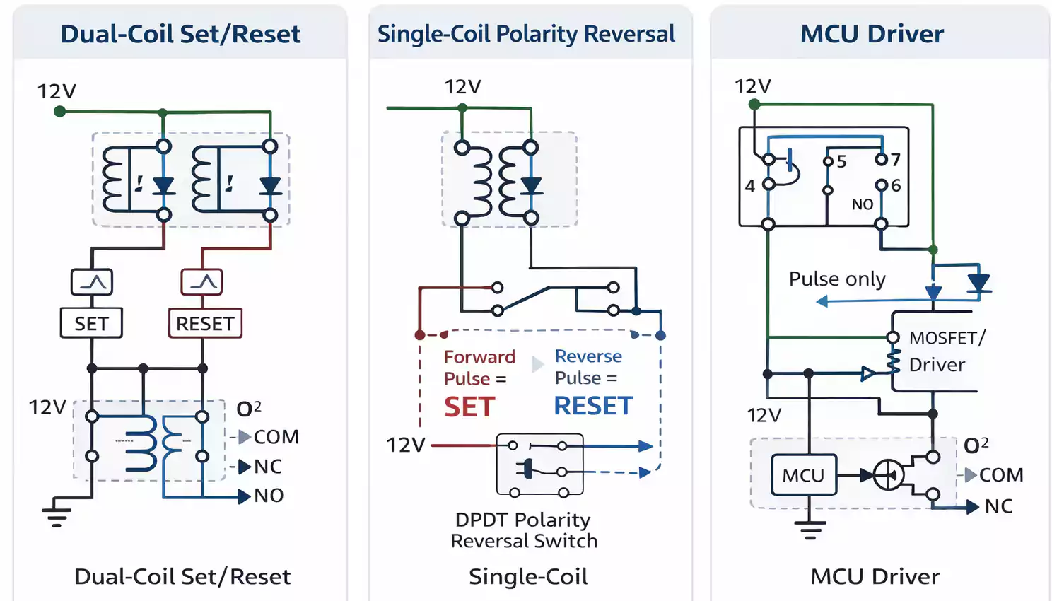
Example 1 — Dual-Coil Set/Reset Wiring
For a dual-coil latching relay, connecting two momentary pushbuttons works well:
- Set Button → triggers Set coil.
- Reset Button → triggers Reset coil.
- The relay remains in the new state once either coil is pulsed.
This approach is simple and reliable because each coil has a dedicated function.
Example 2 — Single-Coil Polarity Reversal Wiring
This wiring uses a single-coil latching relay driven by a polarity-reversal circuit, often achieved with a DPDT switch or an H-bridge. When the polarity flips:
- Forward pulse → Set (ON)
- Reverse pulse → Reset (OFF)
This is more compact (one coil instead of two) but requires careful polarity management.
Example 3 — MCU-Driven 12V Relay
If you’re controlling the relay with a microcontroller (like Arduino or similar):
- Use a transistor or MOSFET to switch 12V to the coil.
- Drive the transistor base with a PWM-capable MCU pin.
- Include a diode across the coil to protect against back-EMF.
- For polarity reversal, use an H-bridge driver interface.
This method provides programmable control over set/reset sequences and allows your system to change state automatically based on logic, timers, or sensor inputs.
How to Choose the Right Latching Relay
When selecting a latching relay — especially a 12V model — here are the most important parameters:
Coil Voltage
Choose a relay with a 12V coil rating if your system runs on 12V DC. Operating outside the coil’s voltage spec may cause unreliable switching.
Coil Type
- Single-coil: simpler wiring but needs polarity reversal.
- Dual-coil: flexible wiring without polarity reversal.
Contact Configuration
Relays come with different contact forms:
- SPST (single pole single throw)
- SPDT (single pole double throw)
- DPDT (double pole double throw)
Match the contact type to the load you want to control.
Load Ratings
Check the relay’s rated current and voltage on the load side. Always pick a relay with a rating higher than your maximum expected load, especially for inductive or motor loads.
Troubleshooting Common Latching Relay Issues
Even with correct wiring, latching relays can occasionally misbehave. Here’s how to diagnose common problems:
1. Relay Doesn’t Change State
- Check that your set/reset pulse is long enough (but not too long).
- Confirm correct coil voltage.
- Verify correct polarity for single-coil types.
2. Relay Won’t Hold State
- Ensure the coil is not being held in a powered state.
- Look for a power supply sag during pulses.
- For dual-coil relays, confirm that coil pins are not swapped.
3. Contacts Stick or Weld
This can happen if the load generates high surges (e.g., motors or solenoids). Try:
- Adding snubber circuits (RC networks).
- Use a relay with a higher contact rating.
4. Noise or False Switching
Electrical noise on the supply or control line can cause unintended pulses. Use:
- Decoupling capacitors.
- Shielded wiring.
- Proper grounding.
Applications Where Latching Relays Shine
Latching relays are especially useful when:
- You need to retain a state after power loss (memory function).
- Power conservation is critical because they don’t draw continuous coil current.
- You’re controlling devices using intermittent control signals.
- You want a stable mechanical switch action without continuous energy use.
Common use cases include:
- Automotive control (door locks, lighting logic, battery isolation).
- Solar or battery backup controllers.
- Remote or wireless switching systems.
FAQ — Quick Answers
Do latching relays need constant power?
No. They maintain their position even after the control signal is removed.
Can a latching relay fail open or closed?
Yes, like any mechanical device, wear and tear can eventually cause failure. Choose a relay rated for more cycles than your expected usage.
Should I use a latching relay instead of a regular one?
Use latching when you want state retention without continuous power. For simple on-off control in mains-powered systems, a regular relay may suffice.
How long should the control pulse be?
Short enough to switch the state but not to overheat the coil. Check the datasheet for recommended pulse durations.
Is polarity important for all latching relays?
Only for single-coil types — where polarity determines set vs. reset. Dual-coil relays don’t require polarity reversal.
Final Thoughts
A latching relay is a versatile and efficient switching solution for power savings and state retention. Whether you’re working on DIY electronics, automotive systems, or industrial automation, understanding how latching relays operate and how to wire them correctly — especially at 12V — can streamline your design and avoid common pitfalls.
With the wiring examples, troubleshooting guidance, and selection tips above, you’ll be ready to implement latching relays confidently in your next project.
