


In modern surface-mount technology (SMT) assembly, resistors are among the most common passive components.
Within this family, SMT resistor networks—also known as resistor arrays or integrated resistor packages—play an important role in high-density, high-precision PCB designs.
This article explains their structure, classification, packaging types, and practical use cases, along with an overview of SMT potentiometers used for adjustable resistance.
What Is an SMT Resistor Network?
An SMT resistor network integrates multiple resistors with identical or proportional values inside a single package.
These resistors are internally connected according to a defined circuit configuration, reducing board space and improving performance consistency.
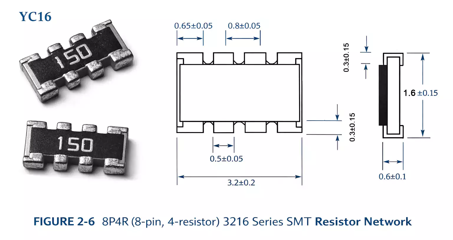
For example, an 8P4R (8-pin, 4-resistor) 3216-series resistor network comprises four discrete resistors packaged into a single compact SMT component.
Such integration not only saves PCB real estate but also improves thermal matching and reduces production complexity.
Structural Classifications
Depending on their design and application, resistor networks can be categorized into four main structural types:
| SOP Type | Shaped like small IC packages; ideal for wave soldering | Analog circuits, filters |
| Chip Power Type | Handles higher power and offers good heat dissipation | Power dividers, current sensing |
| Chip Carrier Type | Enhanced stability and mechanical strength | Communication and test equipment |
| Chip Array Type | The most common SMT form; highly integrated | Digital logic, pull-up/down networks |
Among these, the chip array type is the most widely used due to its standardized SMT-friendly form and compact layout.
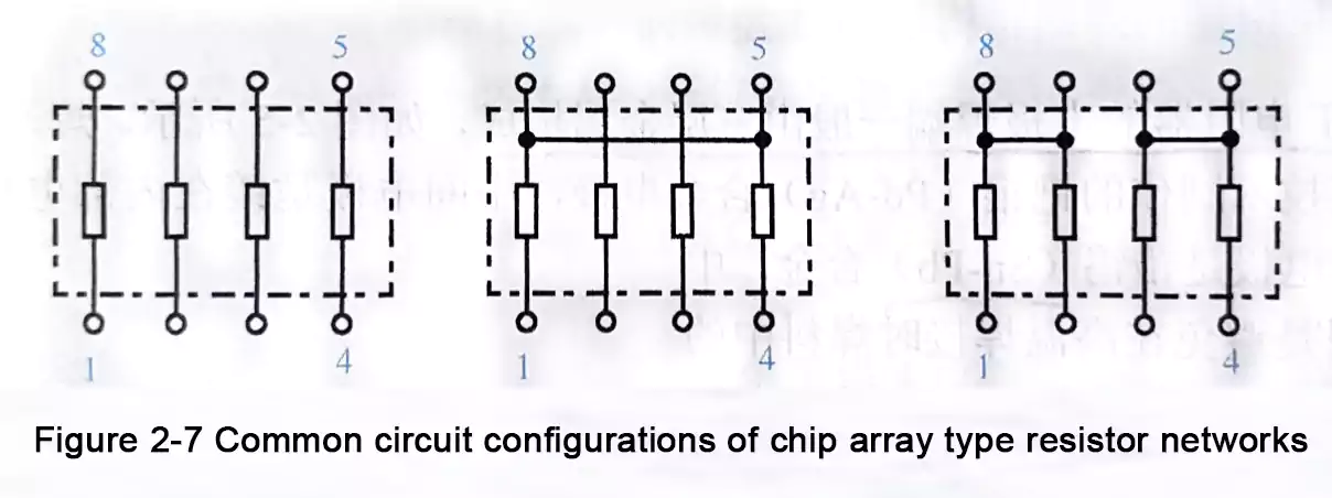
Common Circuit Configurations
Different resistor network packages may feature various internal connection schemes depending on circuit requirements.
Typical configurations include (see equivalent of Figure 2-7):
- Isolated Type: Each resistor functions independently.
- Bussed / Common Type: Multiple resistors share one common node, commonly used for pull-up or pull-down arrays.
- Divider Type: Internal resistors connected in series for voltage division or sensing.
- R-2R Ladder Type: Used in digital-to-analog conversion (DAC) networks for precise voltage scaling.
These structures make resistor networks highly versatile across analog and digital PCB applications.
Package Sizes and Marking
Small fixed resistor networks typically use standard rectangular chip packages such as:
- 0603, 0805, 1206, and 3216 series
Each resistor network is labeled with a numeric code similar to a standard SMD resistor—for example, “103” indicates 10 kΩ.
Common tolerance codes include:
- J (±5%)
- G (±2%)
- F (±1%)
The use of industry-standard marking ensures easy identification and compatibility in automated SMT assembly lines.
Key Performance Characteristics
| Resistance Range | 10 Ω – 1 MΩ | Depends on network design |
| Power Rating | 0.05 W – 0.25 W | Per resistor element |
| Temperature Coefficient | ±100 ppm/°C | Good matching and stability |
| Tolerance Matching | up to ±0.1% | For precision circuits |
Advantages:
- Excellent resistor matching for signal accuracy
- Compact footprint for dense PCBs
- Simplified placement and soldering process
- Improved reliability in high-speed signal designs
Typical Applications
SMT resistor networks are widely used in:
- Microcontroller I/O pull-up and pull-down arrays
- Data bus termination (I²C, SPI, CAN)
- A/D and D/A converter divider circuits
- Signal filtering and attenuation networks
- Voltage sensing and power monitoring modules
These applications highlight how integrated resistor arrays improve circuit performance and assembly efficiency.
SMT Potentiometers Overview
In addition to fixed resistor networks, SMT potentiometers—also known as chip potentiometers—are adjustable resistive devices used for fine-tuning circuit parameters.
Key Specifications:
- Resistance Range: 100 Ω – 1 MΩ
- Tolerance: ±25%
- Power Rating: 0.05 W – 0.5 W
- Adjustment Characteristic: Linear (B taper)
Structural Types of SMT Potentiometers
1. Open Type
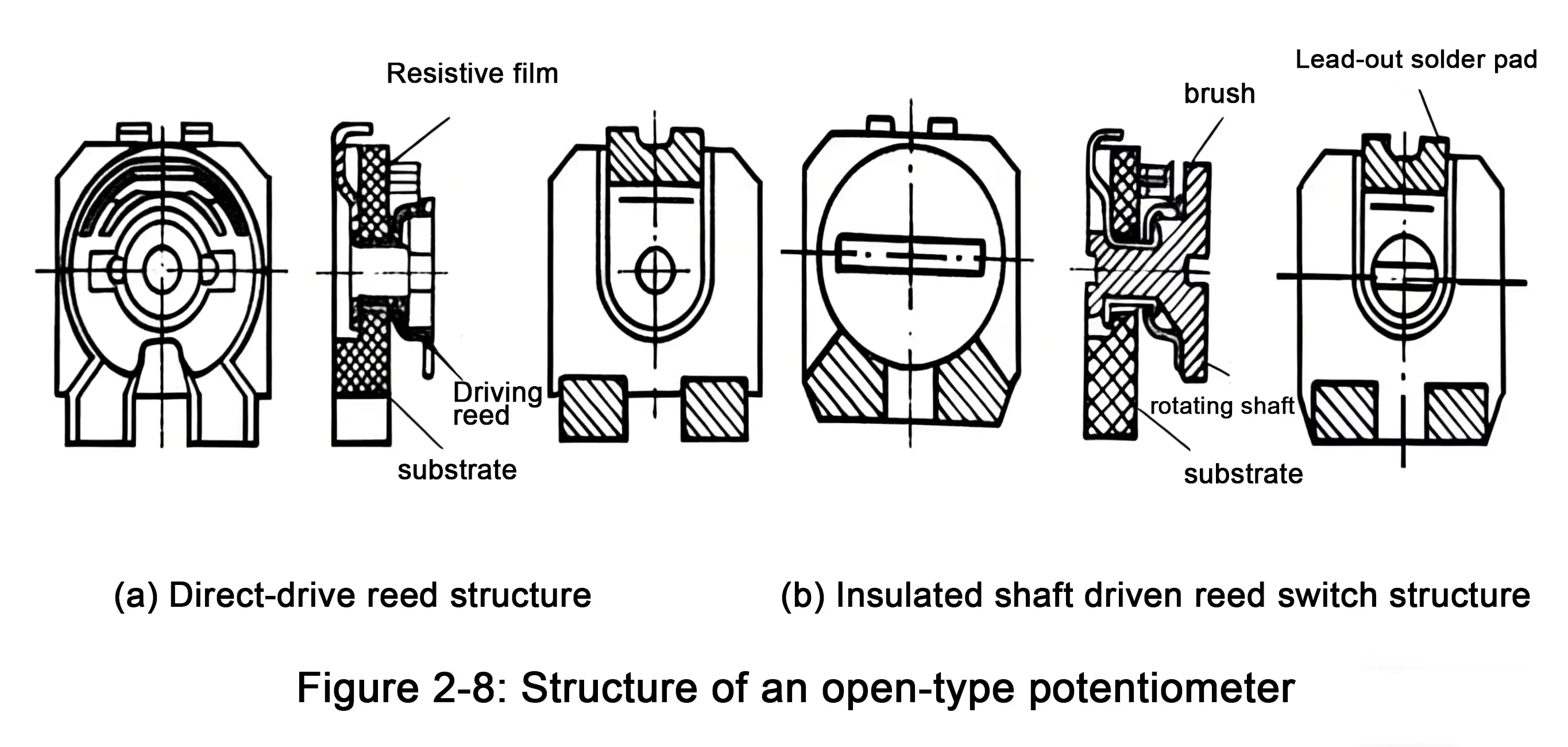
Open-frame potentiometers (see Figure 2-8) feature simple spring contacts with no housing protection.
They are cost-effective but susceptible to dust and moisture.
Best suited for consumer electronics and reflow soldering only—not recommended for wave soldering.
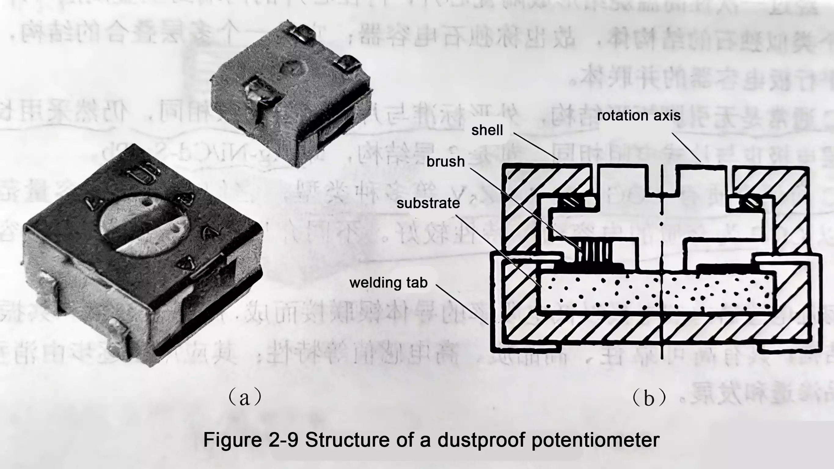
2. Dustproof Type
As shown in Figure 2-9, these include a protective cover that prevents contaminants from entering.
They offer better reliability and are often used in industrial or high-end consumer equipment.
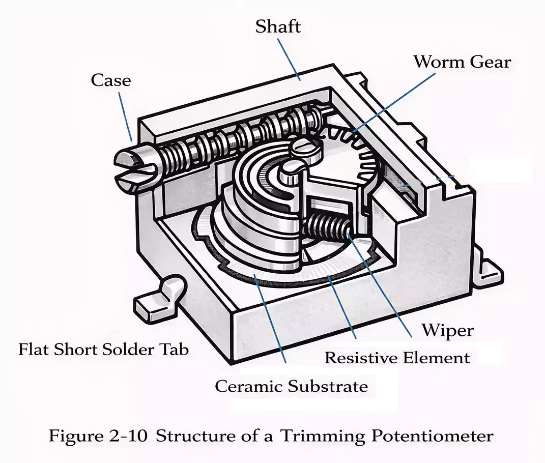
3. Trimming Type
Precision trimmer potentiometers (Figure 2-10) allow fine-tuning and calibration with high accuracy but cost more.
Commonly used in instrumentation, telecom, and control systems.
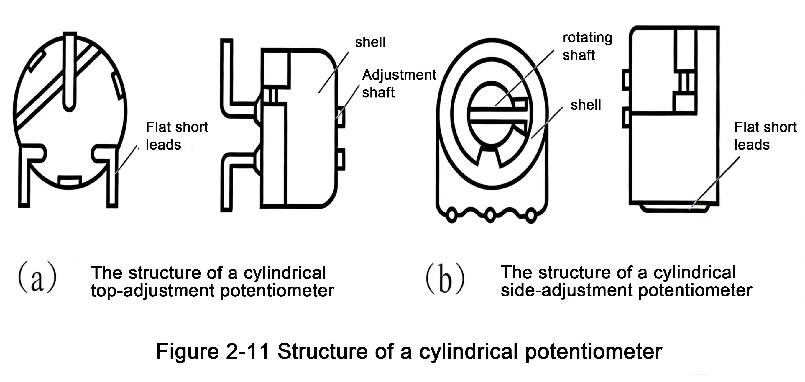
4. Fully Sealed Type
Fully sealed potentiometers (Figure 2-11) are available in cylindrical or flat rectangular forms, with top- or side-adjust versions.
They offer excellent sealing, long life, and reliable adjustment performance.
Summary
Both SMT resistor networks and SMT potentiometers are essential components in modern electronics.
Resistor networks provide compact, consistent, and cost-effective solutions for fixed resistor arrays, while potentiometers enable adjustable calibration in analog and digital circuits.
Understanding their structures, circuit types, and packaging standards helps engineers design more reliable, high-density, and manufacturable PCBs.
