


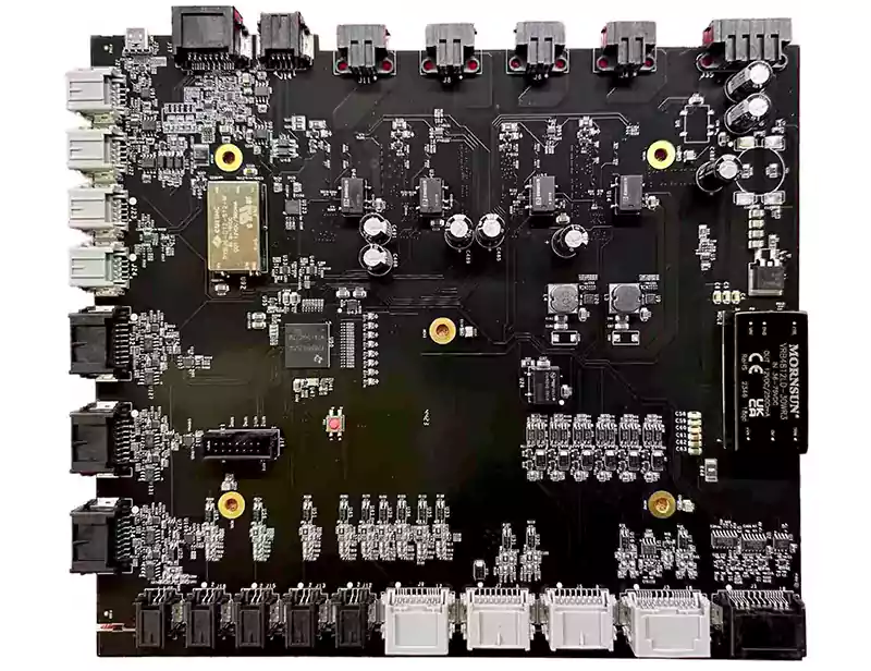
In electronics design, black PCBs are often associated with premium products. Their clean and minimalist appearance makes them a common choice for flagship consumer devices and high-visibility circuit boards in high-end applications.
But beneath that sleek matte surface lie unique manufacturing and inspection challenges. Choosing a black PCB isn’t just about color; it affects solder mask performance, AOI inspection, silkscreen readability, and even ground-plane visibility during debugging.
This guide explains what a “black PCB” is, how it differs from black-core FR-4, and key considerations for solder mask, silkscreen color, and grounding when using black laminates.
What Does “Black PCB” Really Mean? Black Solder Mask vs. Black-Core FR-4
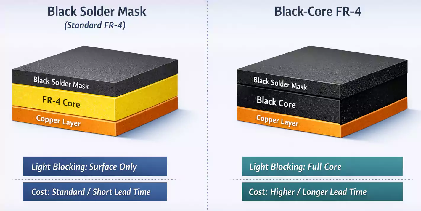
When people say “black PCB,” they usually mean a standard FR-4 board with a black solder mask. The copper traces and substrate are the same as any other board — it’s the thin polymer solder mask layer that provides the dark finish.
A less common variant is the black-core FR-4 laminate, in which the substrate (glass-epoxy resin) is dyed black throughout its thickness. This creates an even darker edge and completely eliminates light transmission.
Key differences:
| Light Blocking | Surface only | Full core opacity |
| Cost & Availability | Standard | Expensive, limited supply |
| Fabrication Lead Time | Normal | Longer (special stock) |
| Visual Appeal | High | Premium / deep black edge |
For most applications, a black solder mask gives the desired look without the extra cost of black-core material.
However, for optical or camera modules that require stray light to be completely absorbed, black-core FR-4 may be justified.
Why Choose Black PCBs?
Black PCBs are chosen for three main reasons:
- Aesthetics and Branding – A dark finish gives products a high-end look. Brands like Apple and Razer often use black or dark matte boards where the PCB is visible through vents or transparent cases.
- Optical Performance – Black surfaces absorb light and reduce internal reflections, ideal for LED displays, sensors, and camera modules.
- Differentiation – In product demos or investor prototypes, a black PCB simply looks more finished and professional.
However, these advantages come with trade-offs in inspection, readability, and manufacturability.
Manufacturing and AOI Challenges
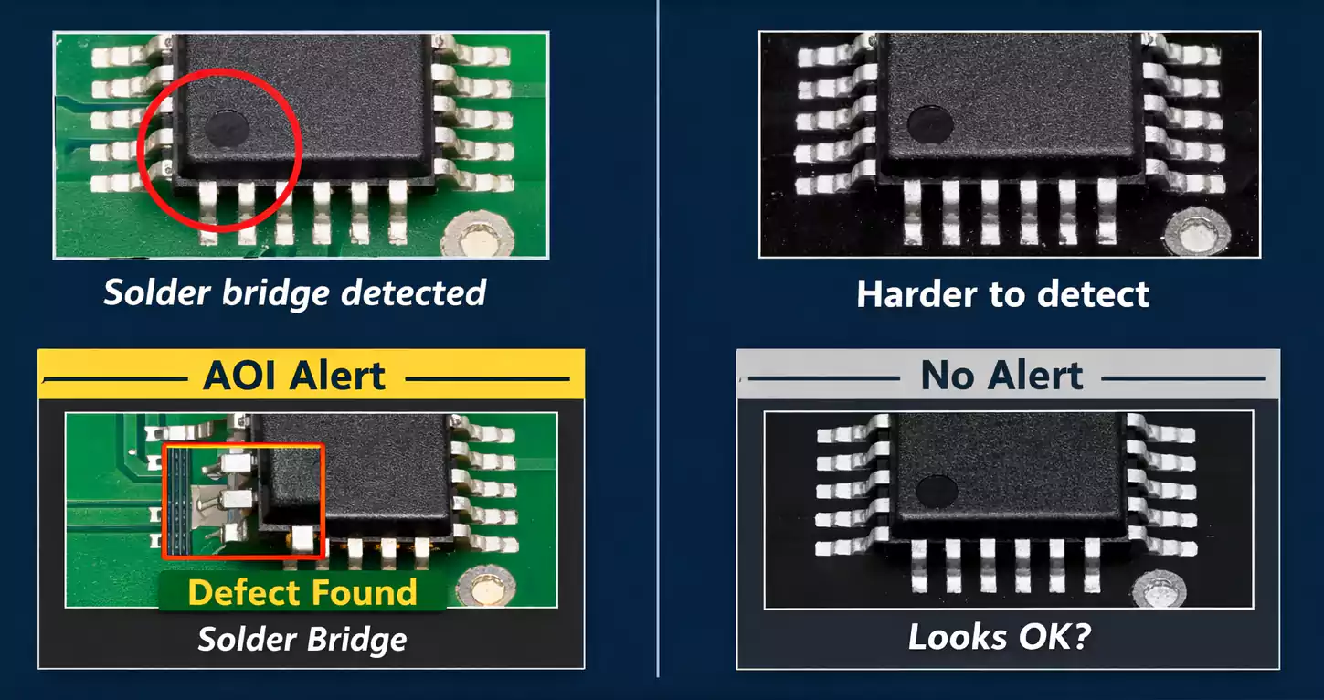
1. Lower AOI Contrast
Automated Optical Inspection (AOI) systems rely on high contrast between copper, solder mask, and silkscreen.
On black PCBs, reflected light and low contrast make defect detection harder. Fine solder bridges, missing pads, or misaligned components may go unnoticed.
To compensate, manufacturers often increase AOI sensitivity or supplement it with manual visual inspection — both of which add time and cost.
2. Narrower Process Window
Black solder mask pigments absorb more UV light during exposure and curing, which can slightly reduce the process latitude. Overexposure can lead to brittle masks or surface gloss variations.
That’s why consistent oven profiles and controlled exposure energy are critical during manufacturing.
3. Longer Lead Time for Black-Core FR-4
If you specify a black-core laminate (instead of just a black mask), expect a longer procurement cycle. These materials aren’t typically in stock and require special orders from laminate vendors.
Readability and Rework: The Downside of Black Ink
Once your board reaches assembly, another challenge appears — readability.
1. Poor Visual Contrast
On a black solder mask, fine white or gray text can blend into the background under bright light.
Operators may struggle to read reference designators or polarity marks, slowing down assembly, inspection, and troubleshooting.
2. Surface Imperfections Stand Out
Black PCBs show fingerprints, scratches, and flux residue much more visibly than green or blue boards. That may not affect function, but it impacts perceived quality — especially for boards used in visible locations.
3. Design Guidelines for Better Readability
To mitigate these issues:
- Use larger silkscreen fonts (≥ 1 mm height, ≥ 6 mil stroke width).
- Keep clear space around text; avoid silkscreen over vias or solder pads.
- Add filled or inverted polarity symbols instead of thin outlines.
- Maintain consistent labeling orientation for ease of assembly.
Applying these layout techniques improves readability during manufacturing and post-processing.
Silkscreen Color and Contrast Recommendations
Your silkscreen color choice has a major effect on usability:
| Black | White | Good (matte mask preferred) | Most common |
| Black | Yellow | Excellent | High-contrast, visual boards |
| Green | White | Excellent | Traditional default |
| White | Black | Highest contrast | LED or display PCBs |
For matte-black PCBs, yellow silk-screen provides the best readability under both daylight and fluorescent light.
If your manufacturer allows it, request a contrast test coupon to compare white vs. yellow silkscreen before production.
Solder Mask Selection: DFM and Reliability Basics
The solder mask is more than just cosmetic — it directly affects manufacturability and solder quality.
1. Process Types
- LPI (Liquid Photo-Imageable) – The standard in nearly all modern PCBs.
- DFSM (Dry Film Solder Mask) – Used in high-volume or fine-pitch designs for more uniform thickness.
Typical cured thickness: 15–25 µm over copper and up to 50 µm over laminate.
2. Design for Manufacturability Tips
- Maintain ≥ 3 mil solder mask dam between pads to avoid solder bridging.
- Use SMD pads for fine-pitch components; NSMD pads are preferred for BGAs when tolerances allow.
- Decide whether to tent, plug, or cap vias — tented vias prevent solder wicking during reflow but may trap air; plugged vias are better for reliability.
- For black masks, specify a matte finish to reduce glare and improve AOI consistency.
Ground Plane Fundamentals for Black PCB
While the solder mask color doesn’t directly affect signal integrity, it can make it easier for engineers to see and validate ground connections during debugging.
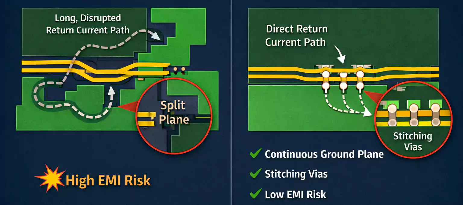
1. Why Ground Planes Matter
A continuous ground plane provides a low-impedance return path for high-speed signals and acts as a natural EMI shield.
Breaking or slotting the ground plane forces return currents to detour, increasing loop area and radiated noise.
2. Visual Limitations with Black Boards
During prototype bring-up, identifying copper splits or via grids through a black mask is difficult.
If you frequently debug or modify boards, request an engineering-view file from your PCB vendor—a color-inverted image showing plane segmentation. It helps technicians trace invisible return paths beneath the dark coating.
3. Practical Grounding Tips
- Keep all high-speed traces directly above a solid reference plane (GND or power).
- Place stitching vias (ground vias) every 10–15 mm across plane boundaries.
- Avoid crossing slots in the ground plane.
- For optical devices, consider grounding the metallic housing or shielding to suppress radiated EMI.
Even on a black PCB, a well-designed grounding scheme remains your best tool for signal integrity and EMC compliance.
Thermal and Optical Behavior: Don’t Overrate the Color
A common myth claims that black PCBs “run hotter.”
In reality, the color of the solder mask has minimal effect on overall board temperature. Thermal performance depends on copper thickness, via count, and heat-spreader design, not pigment.
Black surfaces do have slightly higher emissivity (better radiative cooling), but the effect is negligible at typical PCB operating temperatures. The major heat path is still conduction through copper and components.
On the optical side, black coatings can significantly reduce light reflection and leakage, which is why camera modules and sensor PCBs often specify black solder mask or black-core FR-4.
Cost and Lead-Time Considerations
Choosing black shouldn’t surprise your finance department — but there are real cost differences:
- Solder Mask: Black LPI ink is marginally more expensive than green LPI ink (5–10% difference).
- AOI & Rework: Increased inspection time adds labor cost.
- Black-Core FR-4: Material and lead time can increase total cost by 20–40 %.
For mass production, always confirm with your fabricator whether the pigment affects turnaround time or panel yield.
In most cases, green remains the most cost-efficient and process-stable color.
When to Choose Black — and When to Stay Green or White
| Visible consumer boards | Black (matte) | Aesthetic, brand identity |
| Optical / camera modules | Black-core FR-4 | Stray light suppression |
| Cost-sensitive mass production | Green | High yield, standard process |
| LED lighting or high visibility | White | Reflectivity, brightness |
| AOI / Debug-intensive boards | Blue or Green | Easier inspection |
In short, choose black only when appearance or optical function outweighs the cost and inconvenience of inspection.
Frequently Asked Questions
Is a black PCB higher quality than a green one?
No. Color only affects appearance and manufacturability, not performance.
Does black color increase temperature?
No significant difference. Thermal behavior is dominated by copper and stack-up design, not mask pigment.
Why is a black PCB harder to inspect?
Low contrast between solder joints, traces, and mask color makes AOI less effective and slows visual inspection.
When should I use black-core FR-4?
Only when complete light blocking is required, such as in cameras, sensors, or optical instruments.
Conclusion
Black PCB looks stunning, but they demand respect in manufacturing.
Choosing the right solder mask type, silkscreen color, and layout rules is essential to preserve both aesthetics and reliability. Combine that with sound ground-plane design, and you’ll achieve a product that performs as well as it looks.
