


When you hear the term “PCB mount,” it can mean two very different things depending on who’s talking.
In electronics manufacturing, it refers to the mechanical installation of a printed circuit board into a product enclosure.
In the mechanical-keyboard community, it describes how switches or stabilizers are attached — either directly to the PCB or supported by a top plate.
This guide explains both meanings. We’ll start with PCB mounting techniques used in product design and then cover how “PCB-mount” and “plate-mount” switches differ.
What Is PCB Mounting?
In the manufacturing world, PCB mounting refers to securely mounting a printed circuit board within a mechanical frame, chassis, or case using hardware such as screws, standoffs, clips, or rails.
It’s not just about keeping the board in place — proper mounting directly affects electrical reliability, thermal performance, and long-term durability.
A poorly supported PCB can flex during assembly or vibration, stressing solder joints and causing micro-cracks that lead to intermittent failures.
Mounting methods also influence insulation distance, creepage clearance, EMI shielding, and service access.
In short, good PCB mounting makes the difference between a product that passes qualification tests and one that fails in the field.
Common PCB Mounting Methods
Every mechanical setup must balance cost, ease of assembly, shock resistance, and maintenance requirements. Below are the most common mounting techniques found in consumer and industrial designs.
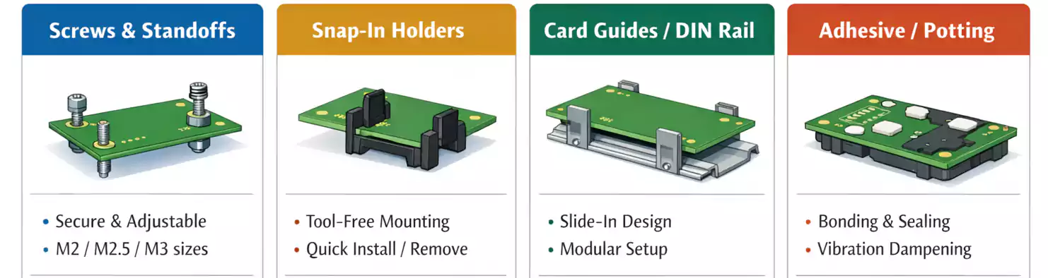
1. Screw and Standoff (Spacer) Mounting
The most universal and dependable method is using screws and standoffs — cylindrical spacers that maintain a fixed height between the PCB and the chassis or another board.
They’re typically made of nylon, brass, aluminum, or stainless steel, with metric threads such as M2, M2.5, or M3.
Advantages:
- Excellent mechanical strength and electrical grounding when using metal hardware.
- Precise control of PCB height and alignment.
- Easy to assemble and disassemble for servicing.
2. Snap-In Clips and PCB Holders
For quick assembly without tools, many plastic housings use snap-in clips or PCB holders. These clips lock the board into place by friction or detent, holding it firmly while still allowing removal for maintenance.
Pros:
Fast installation, reduced assembly time, and no loose hardware.
Cons:
Limited load capacity; clips can fatigue over time or loosen under vibration. Use clips for lightweight PCBs or frequently serviced modules to ensure stress is absorbed by the enclosure rather than the solder joints.
3. Rails, Guides, and DIN-Rail Systems
In rack-mounted or modular products, PCBs often slide into card guides or DIN rails.
This method allows hot-swapping and easy replacement without disassembling the chassis.
Applications:
Telecom systems, industrial control racks, and laboratory instruments.
Considerations:
Provide end stops or latches to prevent movement under shock or vibration, and use conductive rails for grounding if required.
4. Adhesive Pads, Potting, and Cushion Mounts
When mechanical fasteners aren’t possible — such as in compact consumer electronics or sealed environments — engineers may use adhesive pads, silicone cushions, or potting compounds to hold the board in place.
While these methods offer vibration damping and moisture protection, they reduce serviceability and may cause rework difficulties.
Choose adhesives with known long-term aging performance and verify thermal resistance under continuous load.
Mounting Hole and DFM Guidelines
Mounting holes are simple in appearance but critical to both mechanical and electrical reliability.
Follow these best practices during layout:
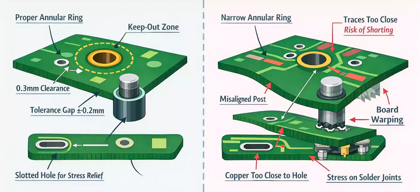
- Hole Size and Annular Ring
- Match plated or non-plated hole diameters to your hardware.
- For plated mounting holes, leave an annular ring of at least 0.3 mm and avoid routing traces close to the hole edge.
- Avoid ground planes under metallic standoffs unless intentional grounding is required.
- Tolerances and Alignment
- Account for manufacturing tolerances in both PCB fabrication and enclosure machining.
- Provide ±0.2–0.3 mm clearance between hole centers and mechanical posts to prevent stress during assembly.
- If multiple boards are stacked, use floating or slotted holes to relieve misalignment.
- Stress Path Control
- Place heavy or connector-bearing components close to mounting points to minimize bending.
- Ensure insertion and removal forces (from cables or connectors) are transmitted to the chassis rather than solder joints.
- Creepage and Clearance
- Maintain adequate spacing between mounting hardware and high-voltage nets.
- Use insulating washers when metal screws pass near live circuits.
Following these DFM guidelines ensures a consistent assembly yield and reduces the risk of cracks or lifted pads after thermal cycling.
Choosing the Right Mounting Hardware
Mounting accessories come in many forms — standoffs, spacers, screws, washers, insulating pads, or dedicated PCB holders. Choosing the correct combination depends on your application’s environment and service requirements.
| Standoff/Spacer | Nylon, Brass, Aluminum | Precise spacing, strong support | General electronics, power supplies |
| Screw + Washer | Steel, Stainless | Reliable clamping | Industrial & automotive assemblies |
| Snap Clip / Holder | ABS, POM, Nylon | Tool-free assembly | Consumer devices, modular boards |
| Adhesive Pad / Cushion | Silicone, Acrylic | Shock damping, isolation | Portable or sealed devices |
Selection principles:
- Match the pillar height to component clearances and connector positions.
- Confirm dielectric strength and flammability rating (e.g., UL94 V-0 for plastics).
- Consider accessibility for maintenance — a perfect mount is useless if it blocks connectors or cables.
The Keyboard Perspective: PCB-Mount vs Plate-Mount
Now let’s switch to the other common meaning of PCB mount — the one used in mechanical keyboard design.
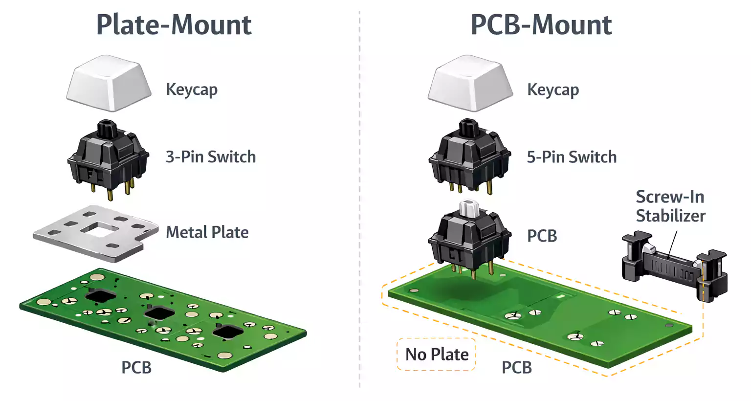
Switch Mounting Styles: 3-Pin vs 5-Pin
Mechanical switches such as Cherry MX, Gateron, and others come in two mounting styles:
- PCB-mount (5-pin):
These switches have two metal contact pins and three plastic locating legs. The extra legs anchor directly into the PCB, increasing stability.
PCB-mount designs allow “plateless” builds where switches are soldered directly to the board, providing a softer, quieter typing feel. - Plate-mount (3-pin):
These switches rely on a metal or plastic top plate to keep them aligned. The switch housing lacks the two outer plastic legs, and the plate absorbs most of the mechanical stress.
Plate-mount keyboards feel stiffer and are easier to hot-swap or replace switches, since alignment doesn’t depend solely on solder joints.
Stabilizer Mounting: Screw-In vs Plate-Clip
Large keys (Space, Enter, Shift) use stabilizers to balance the keycap and reduce wobble.
Here again, two main mounting styles exist:
- PCB-mount stabilizers: Screw-in or snap-in versions that attach directly to the PCB. They provide better rigidity and quieter operation, but require the PCB to have matching cutouts.
- Plate-mount stabilizers: Clip onto the metal plate, simpler and cheaper but slightly noisier and easier to misalign.
If your PCB supports screw-in stabilizers, they’re generally preferred for enthusiasts seeking tighter tolerance and less rattle.
Sound, Feel, and Maintenance
Real-world reviews show that the biggest difference between PCB-mount and plate-mount keyboards is stability, not sound.
A plate adds structural rigidity, producing a firmer keypress. PCB-mount builds without a plate offer a “flexier” and more cushioned feel that many custom builders enjoy.
For everyday use:
- Frequent modders / hot-swap boards → PCB-mount for easier component replacement.
- Fixed builds / maximum rigidity → plate-mount.
Ultimately, both can deliver excellent results when built with quality switches, stabilizers, and proper tuning.
Frequently Asked Questions
Q1: What is PCB mounting, and why is it critical?
It’s the mechanical process of fixing a printed circuit board to an enclosure. Proper mounting prevents solder stress, ensures safety clearances, and enhances vibration and thermal reliability.
Q2: How do I size and place mounting holes?
Follow your hardware’s recommended hole diameter (e.g., 3.2 mm for M3). Keep copper at least 0.5 mm away from the hole edges, and provide tolerance room to prevent assembly stress.
Q3: PCB-mount vs Plate-mount — which should I choose?
For keyboards, choose PCB-mount if you value customization, modding, and a softer typing feel; choose plate-mount if you want structural stiffness and easy maintenance.
Q4: Do screw-in stabilizers really make a difference?
Yes. Screw-in stabilizers eliminate lateral play and reduce noise, but only if your PCB includes the proper mounting holes.
Conclusion
The phrase “PCB mount” bridges two worlds — mechanical engineering and mechanical keyboards — but the underlying principle is the same: stability through precision.
In electronics, it ensures your circuit survives vibration, heat, and assembly stress.
In keyboards, it defines how your keys feel and sound.
By understanding mounting methods, choosing the right hardware, and respecting mechanical tolerances, you can create products — or keyboards — that last longer, perform better, and feel exactly as they should.
