


In PCB assembly manufacturing, advanced equipment alone does not guarantee high product quality. What truly defines production capability and reliability is a well-designed SMT (Surface Mount Technology) production system—an integrated structure in which process engineering, automation, and management work in harmony.
This article provides a clear overview of SMT production systems, their major components, and how different line configurations enable efficient, high-quality PCB assembly.
What Is an SMT Production System?
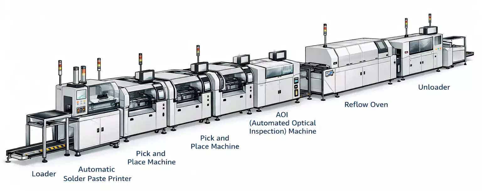
An SMT production system is more than a single piece of equipment. It’s a fully automated assembly line, with multiple surface-mount machines connected in sequence to perform each step of the process — from solder paste printing to inspection.
A mature SMT production system typically features:
- Seamless connection between each process stage
- Automatic PCB transfer between machines
- Stable, repeatable process control
- Integrated inspection, rework, and data-traceability functions
In essence, an SMT system transforms process design into reliable, large-scale manufacturing capability.
Core Components of an SMT Production System
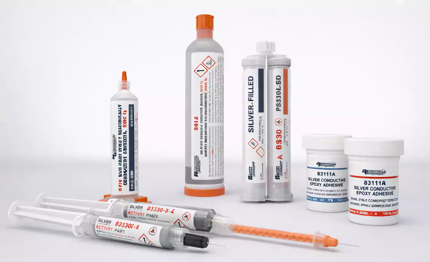
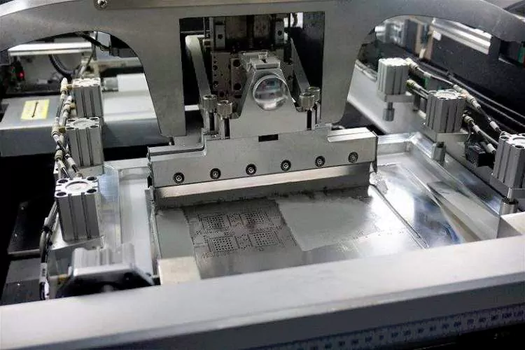
1. Coating and Printing Equipment
This stage applies solder paste or adhesive onto the PCB pads — the starting point of SMT manufacturing.
Common equipment includes:
- Solder paste printers
- Dispensing machines
Consistent, precise printing directly affects placement accuracy and final solder joint quality.
2. Placement Equipment
Placement machines ("pick-and-place") position surface-mount components accurately on the PCB.
Typical configurations include:
- High-speed placement machines for small, standardized components
- Multi-function placement machines for larger or irregular parts
These machines work together to balance throughput, accuracy, and flexibility.
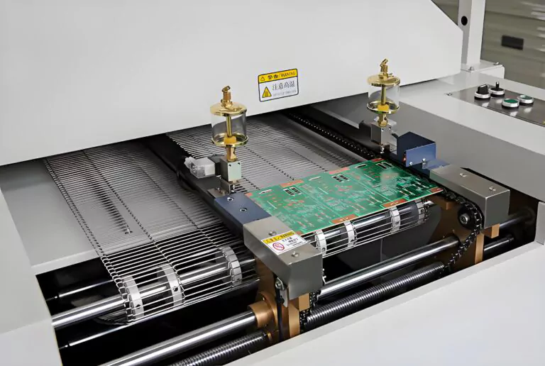
3. Soldering Equipment
Soldering equipment establishes both electrical and mechanical connections between components and the PCB.
Common systems include:
- Reflow ovens — the standard in SMT processes
- Wave soldering machines — used for hybrid or through-hole assemblies
Different soldering methods are selected based on board design and component type.
4. Cleaning and Inspection Equipment
To ensure assembly quality, SMT lines incorporate cleaning and automated inspection systems such as:
- AOI (Automatic Optical Inspection)
- X-ray inspection systems
- In-circuit and functional test equipment (ICT/FCT)
These tools detect soldering defects, bridging, and misalignments early in the process, preventing faulty boards from progressing.
5. Rework Equipment
Even with strict control, occasional defects occur. Rework equipment repairs faulty boards using:
- Hot-air or infrared rework stations
- Localized heating systems
Proper rework capability helps maintain high yield without compromising board reliability.
6. Conveying and Control Systems
Automated conveyors link all process stages, allowing boards to flow smoothly across the production line.
In parallel, line control systems manage:
- Process synchronization and cycle time
- Equipment communication and data exchange
- Production and quality traceability
Stable conveying and intelligent control systems are key to achieving continuous, automated SMT production.
Relationship Between SMT Processes and Equipment
Each type of equipment in the SMT system corresponds directly to a specific manufacturing process:
| Solder paste application | Printer, dispenser |
| Component placement | Pick-and-place machine |
| Soldering | Reflow oven, wave solder machine |
| Cleaning | Solvent or aqueous cleaner |
| Inspection | AOI, X-ray, ICT/FCT |
| Rework | Hot-air or infrared rework station |
Proper equipment configuration ensures that each process step is executed consistently and controllably — a cornerstone of high-quality PCB assembly.
Common SMT Line Configurations
1. Single-Line SMT Production
A simple, flexible setup ideal for:
- Small- to medium-batch production
- Frequent product changeovers
This configuration supports rapid prototyping and short production cycles.
2. Dual-Line SMT Production
Two SMT lines running in parallel increase throughput and equipment utilization, making this layout ideal for:
- Large-volume production
- Stable, high-demand product lines
3. Hybrid Assembly Lines (SMT + THT)
When a board includes both surface-mount and through-hole components, a hybrid line is used.
This layout combines SMT and wave-soldering stations to handle mixed-technology requirements, common in industrial control and communication equipment.
4. Full Surface-Mount Assembly Line
Fully automated SMT lines handle only surface-mount components.
They are widely used for:
- High-density, miniaturized products
- Consumer electronics and advanced industrial systems
Such lines require top-tier placement precision and stable process control.
How Line Design Impacts Manufacturing
The structure and organization of an SMT production line directly influence:
- Production efficiency and output
- Assembly quality and process repeatability
- Adaptability to product variations
A properly designed system balances these factors, enabling reliable, high-efficiency PCB manufacturing.
Conclusion
The SMT production system is the foundation of modern electronics manufacturing.
From coating to inspection and control, every subsystem supports a consistent, high-quality assembly process. A well-engineered SMT system doesn’t just enhance efficiency — it ensures product reliability, supports automation, and sustains competitiveness in today’s fast-moving electronics market.
