


In modern electronics manufacturing, every board needs to be tracked. Adding a QR code PCB is now one of the easiest and most reliable ways to do that.
It enables manufacturers to trace units, manage production data, and connect users to online resources.
This guide covers using QR and Data Matrix codes on PCBs, designing them correctly, and how laser marking enhances traceability as a quality tool.
Why Add a QR Code PCB?
QR and Data Matrix codes have become standard in the electronics industry.
They can carry serial numbers, batch IDs, and date codes and process information directly on the board surface.

Main benefits include:
- Full traceability: Each board gets a unique identity for tracking through SMT, testing, and shipping.
- Process control: Linking production data to MES or ERP systems helps with yield and failure analysis.
- Field support: Technicians or users can scan a board to view documentation, schematics, or registration pages.
In general, Data Matrix codes are more common in industrial use where space is limited, and precision is high, while QR codes are often used for human-readable or external links.
QR Code vs. Data Matrix — Which One to Choose?
Both QR and Data Matrix codes serve the same purpose: they store digital information in a small area.
However, they differ slightly in structure and performance.
| Typical use | Consumer & general traceability | Industrial traceability, small parts |
| Size efficiency | Larger for the same data | Smaller, higher data density |
| Readability | Easy to scan with any smartphone | Requires industrial or 2D scanners |
| Error correction | Up to 30% data recovery | Very strong, reliable on damaged surfaces |
If your product is small or has tight component spacing, Data Matrix is usually a better choice.
If you want users or technicians to scan it with a smartphone, QR is the practical choice.
How to Add a QR Code on PCB — Three Common Methods
1. Silkscreen (Legend Printing)
The simplest method is to print the code on the silkscreen layer with white or black ink. This approach is low-cost and requires no specialized equipment, but it depends heavily on ink contrast and print resolution.
Tips:
- Keep the code away from dense component areas or copper pours.
- Use strong color contrast (white on dark green, or black on white solder mask).
- Avoid very small modules—fine details may be obscured or filled with solder mask.
Silkscreen codes are great for static information, such as product model or version, but not ideal for serialized tracking.
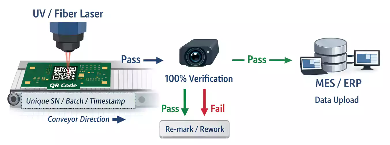
2. Laser Marking
Laser marking is the most precise and professional method for QR or Data Matrix codes on PCBs.
A UV or fiber laser removes a thin layer of solder mask or oxidizes the surface to create a high-contrast mark.
Advantages:
- Permanent and chemical-resistant.
- Extremely fine resolution (can print modules with features as small as 100 µm).
- Works well for unique serial numbers and real-time MES integration.
During production, the laser station can mark each board, and a camera automatically scans and verifies the code before moving to the next step.
3. Labels or Stickers
If the PCB surface is uneven or if the design doesn’t allow printed or laser marks, a high-temperature label can be used.
Labels can survive reflow soldering and cleaning chemicals, but they add small material and assembly costs.
Size and Quiet Zone: Getting It Right
For a code to be readable, size and contrast matter more than anything else.
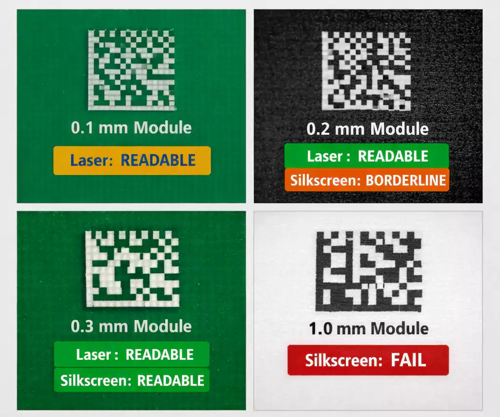
- Minimum module size: For silkscreen, keep each module (the smallest square) at least 0.25–0.3 mm wide.
For laser marking, modules as small as 0.1 mm can still be scanned reliably. - Quiet zone: Leave a clear area around the code at least 10–20% of the code width with no traces, pads, or text.
- Overall size: A finished QR code measuring 10–15 mm square usually scans well at 10–20 cm.
From EDA to Gerber: How to Include the Code in Your Design
Modern PCB design tools like Altium Designer and KiCad allow you to place QR codes directly in the layout.
You can also generate a code as a vector (DXF or SVG) file and import it into your silkscreen layer.
Avoid raster images because they may lose resolution during CAM processing.
Always check the manufacturer’s minimum silkscreen line width and verify that the code contrast is sufficient under your chosen solder mask color.
FAQ
How small can a QR code on a PCB be?
For silkscreen, 10×10 mm is usually safe. With laser marking, you can go down to 5×5 mm or smaller, depending on the material and the camera's resolution.
Can a smartphone read a Data Matrix code?
Some apps can, but built-in camera apps usually only read QR codes. Industrial scanners support both formats.
Can I put the code on an inner layer?
Inner layers are not visible, so only do this for internal alignment marks, not for traceability.
PCB vs. PCBA — When to Add the Code
It’s important to understand the difference:
PCB refers to a bare printed circuit board, while PCBA refers to an assembled board with components.
You can add the QR code at either stage:
- At the PCB factory: Permanent marking before assembly.
- After assembly: Laser or label for final tracking and warranty.
Both are valid — what matters is that each board has a unique, readable identifier throughout its life.
Final Thoughts
Adding a QR code on PCB is no longer just a nice option — it’s a modern requirement for traceability, automation, and customer support.
Whether you use silk screening, laser marking, or labels, follow the proper design rules for size, contrast, and placement.
A well-implemented marking system saves time, reduces errors, and gives every board its own digital identity.
