


Selecting the right PCB material matters. It affects signal quality, thermal reliability, manufacturability, and overall product success. This guide explains the most common PCB materials currently in use. You will learn what each material is and when to use it.
Quick Look: PCB Material Comparison Table
| Standard FR-4 Epoxy | ~140°C | 8–18 / — | Mid | Economic | General purpose |
| Enhanced FR-4 Epoxy | ~140°C | 20–30 / 5–10 | Mid | Better reliability | Multi-layer boards |
| Enhanced Filled FR-4 | ~150°C | 25–45 / 6–12 | Mid | Lower CTE | Better drilling & reliability |
| High-Tg FR-4 | ~175°C | 4–10 / — | Mid | Higher heat tolerance | Lead-free reflow |
| Enhanced High-Tg FR-4 | ~175°C | 30+ / 7–15 | Mid | Heat + reliability | Multilayer high temp |
| Enhanced High-Tg Filled FR-4 | ~175°C | 30+ / 8–16 | Mid | Best CTE control | Complex boards |
| BT/Epoxy Blend | ~190°C | 30+ / 2–8 | Low | Low loss & stability | HDI, backplanes |
| PPO/Epoxy | ~175°C | 30+ / 8–20 | Low | Low loss | RF / Microwave |
| Low Dk/Df Epoxy A | ~200°C | 30 / 6–12 | Low | Low loss | High-speed |
| Low Dk/Df Epoxy B | ~180°C | 30+ / 10–20 | Low | Low loss | High-speed |
| Improved Low Dk/Df Base | ~220°C | 30+ / 15–35 | Low | Low loss | High-rate systems |
| Polyimide (PI) | ~260°C | 30+ / 30+ | Mid | High temp & flex | Flex/rigid-flex |
| Halogen-Free High-Tg FR-4 | ~175°C | 20–30 / 8–12 | Mid | Eco-friendly | Consumer/industrial |
Notes:
Tg = glass transition temperature. Higher means more thermal margin.
T260/T288 = time until delamination at 260°C/288°C reflow. Higher is better.
Dk/Df = dielectric constant & dissipation factor. Lower is better for high-speed signals.
How to Choose a PCB Material
Here is a simple way to pick:
- Start with speed needs:
- Standard boards < 5 Gbps → FR-4 family.
- High-speed nets (10-30+ Gbps) → low Dk/Df or BT/Epoxy.
- Think about heat:
- Lead-free assembly needs higher Tg and T260/T288.
- Multiple reflows require strong materials.
- Consider reliability factors:
- Fillers, low CTE, and good hole quality help reliability.
- Polyimide for high-temp or flex designs.
- Environmental goals:
- Choose halogen-free when needed for compliance.
FR-4 Family Explained
Standard FR-4 and Enhanced FR-4
Standard FR-4 epoxy laminate is the most common. It is low-cost and fine for many designs. Enhanced FR-4 uses better prepregs or fabric to improve thermal or mechanical performance.
Filled and High-Tg Versions
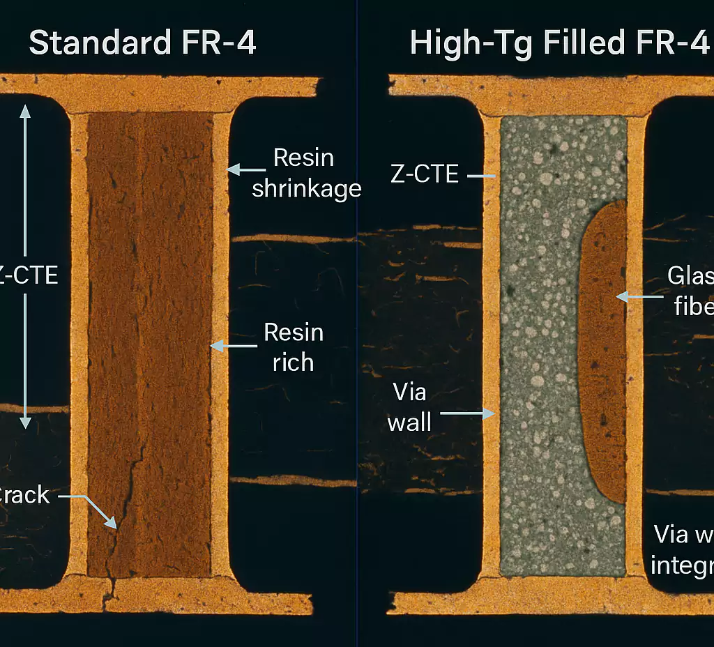
Filled FR-4 adds inert particles that reduce thermal expansion. This helps drilling and hole quality. High-Tg FR-4 has a higher glass transition temperature. It handles lead-free reflow better. Enhanced high-Tg and filled high-Tg combine to improve reliability in complex boards.
Use FR-4 variants for general products, multi-layer boards, and cost-sensitive designs.
Low Dk/Df and Low-Loss Materials
Low Dk/Df Epoxy A and B, Improved Bases
When speed matters, so do the dielectric constant and loss factor. Low Dk/Df blends give better electrical performance than standard FR-4. They are still epoxy-based, so manufacturing is familiar.
Designers choose low Dk/Df when signal integrity is key. These materials suit high-speed digital, high-rate SerDes, and serious data links.
BT/Epoxy Blends
BT/Epoxy blends combine bismaleimide triazine resin with epoxy. They deliver low loss, good thermal stability, and low CTE. These blends are popular in high-density interconnect (HDI) boards and backplane applications.
If your design has fine pitch, dense vias, or heavy copper, BT/Epoxy is worth evaluating.
PPO/Epoxy Materials
PPO (polyphenylene oxide) blended with epoxy reduces losses and maintains good mechanical properties. PPO/Epoxy is common in RF and microwave products. While not as low as PTFE, PPO/Epoxy balances loss, manufacturability, and cost.
Use PPO/Epoxy in communications products where speed and reliability both matter.
Polyimide (PI)
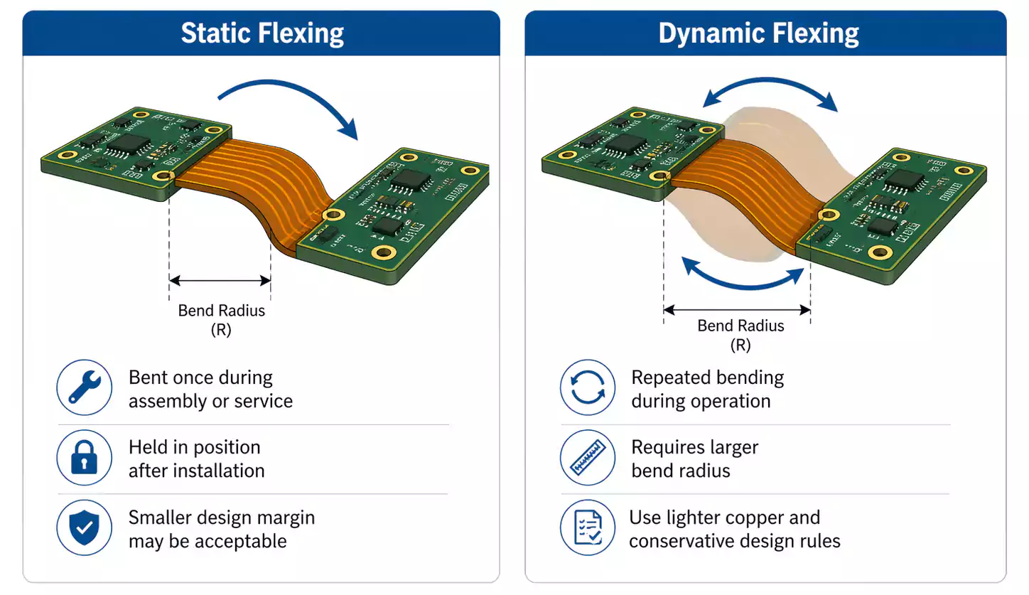
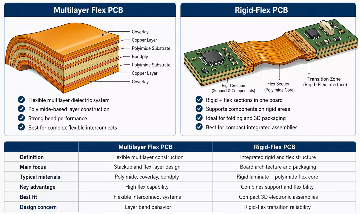
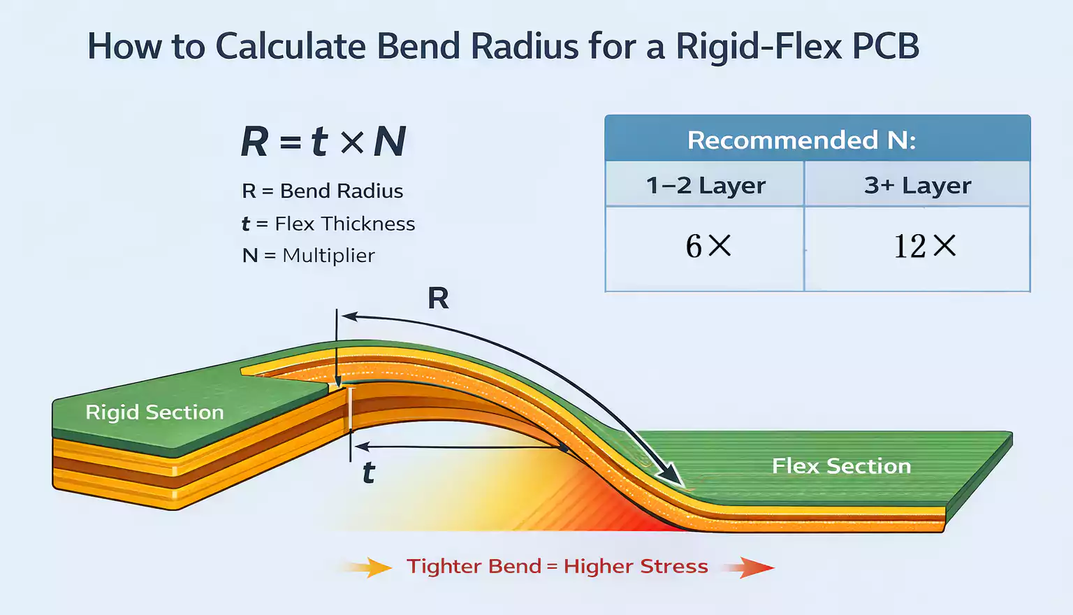
Polyimide is a high-temperature polymer. It has excellent thermal stability and flex performance. Polyimide substrates handle repeated high-temperature cycles and tight bend radii. This makes them ideal for rigid-flex and flex PCB designs.
Note: Polyimide does not always have low Dk/Df, so check electrical specs when using in high-speed links.
Halogen-Free High-Tg Materials
Environmental regulations are driving some designs toward halogen-free laminates. Halogen-free, high-Tg FR-4 uses eco-friendly flame-retardants. It retains many of the performance benefits of standard FR-4 while meeting regulatory goals.
Choose halogen-free when safety standards or customer requirements mandate it.
Key Test Terms Explained
Dk and Df
Dielectric constant (Dk) and loss factor (Df) describe how a material behaves with high-speed signals. Lower is better for high frequency. Be sure to compare values at the same test frequency.
T260 / T288
These are industry-standard thermal reliability measures. Higher values mean the material resists delamination in soldering ovens. For lead-free assembly, higher T260 and T288 are preferred.
Final Thoughts
Choosing the right PCB material can affect signal integrity, thermal reliability, cost, and manufacturability. Start with your performance needs — speed, heat tolerance, board complexity, and environmental goals.
Fast Turn PCBs can help you choose the best material for your design and quickly produce prototypes. Submit your Gerber files today for fast feedback and DFM support.
